

5V Logic Level Errors
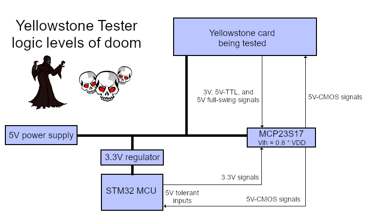
The Yellowstone tester is suffering from the logic level blues. I made a blundering error in its design, which I only discovered now. Like most of my projects, the tester uses a mix of voltages, with the MCP23S17 port expanders running at 5V while the STM32 microcontroller and everything else are running at 3.3V. The card being tested is nominally a 5V device, but it uses TTL signal levels where anything above 2V is considered a logical “1” value. This whole menagerie seemingly worked fine during the tester’s prototyping and development, but it actually has some major problems.
The relevant pins on the STM32 are 5V-tolerant, so that part is fine. Unfortunately I failed to check the input voltage thresholds on the MCP23S17. Now I see that it requires a voltage of at least 0.8 * VDD to detect a logic “1” input value, which means a threshold of 4.0V when VDD is 5V. The STM32 signals are never going to exceed 3.3V, so that’s no good. The so-called 5V signals from the card being tested mostly won’t reach 4.0V either. Some of those signals are driven by 74LS logic with typical high values about 3.4V, and others by 3.3V 74LVC devices.
I’m slightly amazed that I completed the tester prototype, tester PCB, and development of all the tester software without discovering this glaring problem. In fact just yesterday I’d privately declared the tester to be “done”. It was working well, able to program a virgin Yellowstone card and run a large series of functional and electrical tests in just a few seconds’ time. Aside from some rare flakiness I couldn’t reproduce, everything looked good. But then I tried using a different power supply and everything fell apart.
How Did This Ever Work?
With the aid of an adjustable power supply, I eventually found that the tester worked reliably at supply voltages up to 5.05 volts. Above that, the STM32 was unable to communicate with the MCP23S17 port expanders. Some of my other power supplies produce about 5.08 to 5.1 volts with a light load, so that explains why they didn’t work. With a higher VDD, the logic “1” input threshold of the MCP23S17 is also higher, creating a larger shortfall for 3.3V or 5V-TTL signals.
It’s surprising that this ever worked at all. Even at precisely 5.0V, the best case would be a 3.3V signal from the STM32 going into a MCP23S17 input with a 4.0V threshold. A shortfall of 0.7V is pretty large. And yet it did work nicely, at least in this particular circuit, over several weeks of tester development.
Choosing a Voltage
The MCP23S17 port expander can operate with a supply voltage of 5V or 3.3V; I intentionally chose 5V here because the chip interfaces with a card being tested that’s nominally a 5V device, and I was worried about damaging the MCP23S17. Even though most of the output signals from the card should be lower-voltage TTL-level logic signals, at least some of the signals may truly be 5.0 volts. And if the card is defective, which is part of what the tester needs to determine, then any of the card’s signals could be unexpectedly at 5.0V. A chip that’s running at 3.3V can be damaged if 5V is applied to an input pin. If the MCP23S17 has 5V-tolerant inputs then it would be OK, but sadly it doesn’t, so I need to run the chip at 5V to safely read 5V signals. (Probably. See below.)
You can view the MCP23S17 datasheet for the details. In the section for Absolute Maximum Ratings, it says the voltage on all pins should not exceed VDD + 0.6V, and the input clamp current when Vi > VDD should not exceed 20 mA.
How Do I Fix This Mess?
The tester isn’t a product, it’s a tool for developing a product – the Yellowstone disk controller card. I only plan to build three or four testers, and they’ll all be in my possession, or given to whatever PCB assembler I choose to work with. That means I can consider some unconventional fixes here that I would never do on a mass-produced product. If at all possible, I’d like to fix this with some minor surgery to the tester PCB. I really don’t want to design a new tester PCB, add more components and level-shifters, etc. But I need to be confident that the tester is reliable, and if I give one to a PCB assembler, it can’t flake out or give false positives due to minor variations in supply voltage, temperature, or parts substitution on the card being tested.
The fundamental problem is the gap between the 4.0V logic “1” voltage threshold required by MCP23S17, and the lower voltages produced by the STM32 and the card being tested. I either need to raise those voltages up, or lower the MCP23S17 threshold down. None of the possibilities look very promising.
Raising up the lower voltages is basically out of the question. They are what they are, and it would be painful and impractical to insert 5V level shifters on 80-some signals from the card and the STM32.
Lowering the threshold is the only plausible option, which means lowering the supply voltage of the MCP23S17. How much should I lower it, using what method? What other problems might this cause? Should I also lower the supply voltage for the card being tested?
I could lower the MCP23S17 threshold by changing the chip to use a 3.3V supply instead of 5V. But then I would create a new problem where 5V signals might be applied to the chip running at 3.3V, exceeding the absolute maximum rating of VDD + 0.6V and potentially damaging the chip. I could possibly put a series resistor on each of the pins, in order to keep the input clamp current under 20 mA, although this would create some other difficulties and would require making a new PCB.
If I also reduced the supply voltage for the card being tested to 3.3V, it would eliminate the over-voltage concern, but a Yellowstone card won’t work correctly at 3.3V. It has a 74LS244 chip, with a minimum supply voltage of 4.5V.
Diode To The Rescue?
There are no great answers here, but the most promising option I can think of is reducing the supply voltage for the MCP23S17 and for the card being tested to about 4.6V. Using the same voltage for both means there’s no over-voltage risk. At 4.6V the Yellowstone card should still work OK. The reduced voltage would lower the MCP23S17 input threshold to 3.68V, which is still too high, but my tests with the actual hardware show that it should work anyway. The hack-tastic way to get about 4.6V from a 5V source would be using a Schottky or germanium diode to drop a few tenths of a volt. This would be fairly simple to do.
Alternatively I could run the card at 4.6V, but lower the MCP23S17 supply even further to 4.2V, using a second diode. This would still be within the MCP23S17’s absolute maximum rating of VDD + 0.6V, so there shouldn’t be an over-voltage risk so long as the voltages don’t vary too far from their expected values. With a 4.2V supply, the MCP23S17 input threshold would be reduced to 3.36V, which is close enough to 3.3V that I’d be more confident in its reliability.
Complicating all of this is the presence of a 1 ohm sense resistor on the tester’s power supply, which is used for current measurements. Under normal operation, this drops about 50 to 100 mV. If the power supply is nominally 5V, then the MCP23S17 and the card being tested will see a voltage closer to 4.9V.
Another complication is that the 74LS244 on the card being tested will output 5V TTL signal levels, and according to its datasheet, its logical “1” output voltage may be as low as 2.4V. I can’t reduce the MCP23S17 supply voltage far enough to support an input threshold that low. But in practice for a correctly-operating Yellowstone card, and the tester circuitry that’s connected to it, the 74LS244 voltage should be closer to 3.0 – 3.5V, similar to the voltages from the 3.3V STM32.
Using a diode to create intermediate supply voltages is a gross hack, and I don’t like it. It might work during my desk experiments, but then fail later in a different environment. And yet I’m not sure what better alternative I have, unless I’m willing to make major modifications to the tester that will set me back by several weeks. The choices all look bad. I’m embarrassed that I made it this far into tester development without noticing such a fundamental design error.
Read 5 comments and join the conversation5 Comments so far
Leave a reply. For customer support issues, please use the Customer Support link instead of writing comments.
That’s a tough one! If the STM32’s pins going to the port expander are 5V-tolerant you could just add pull-ups to 5V and use the pins in open-drain mode – think I2C. This might not work reliably at higher frequencies (>400 kHz).
I like that idea. It wouldn’t do anything to help the signals from the card being tested, but it would help on the STM32 side. It’s a 9 MHz SPI connection to the MCP23S17, so speed might be an issue. There are four relevant 3.3V signals on the STM32 side: SCK, MOSI, MISO, and CS. The MOSI pin isn’t 5V tolerant, but the others are.
Maybe you could replace the MCP23S17s with MCP23017s and use I2C right away? You’d only need two pins, but would have to deal with setting different addresses.
Or you change the MCP23S17’s supply to 3.3V and add a voltage-translating riser-card between your tester and the DUT. The signals coming from the DUT get a series resistor and zener diode to lower the voltage, the signals going to the DUT a nice driver IC with a 5V supply and 3.3V-compatible inputs.
If I want to lower the voltage to about 4.6V with a diode, maybe I’d be better off using a zener regulator rather than a series Schottky diode with 0.3V to 0.4V drop. That way the lowered voltage would be mostly independent of the input voltage and the load current. 4.7V is a standard zener value, which is probably close enough.
You might consider using an MCP23016. It’s not quite as capable as the later expanders but it does support TTL logic on most pins. I used it recently on a small project (~100 boards) and it turned out to be mire than adequate for basic GPIO.