

Archive for the 'Bit Bucket' Category
Arduino Repair
A brief note about the dead Arduino that I mentioned in the comments of my last post: I received a replacement Arduino, did some troubleshooting, and determined that there were multiple problems. I’d been using the original Arduino successfully to help test-drive my audio circuit before connecting it to BMOW, when in the span of five minutes it went from working to unresponsive. When the replacement Arduino arrived, initially it didn’t work either. I then tried both the old and new Arduinos on a Mac (primary machine is a PC), and also tried replacing the Atmega 168 chip in the original Arduino with a new preprogrammed chip.
What I found surprised me. First off, my PC seems to have lost the ability to download Arduino programs via auto-reset. It works fine on the Mac, but on the PC I have to manually hit the reset button with Ninja-like accuracy at precisely the right moment, about 1.5 seconds after pressing the download button in the software. I know that auto-reset is resetting the board, because I can see the Arduino program restart, but it never transitions to the download step successfully.
The second discovery was that the Atmega 168 in the original Arduino is dead. I don’t know how I killed it, but nothing I could do would revive it, on PC or Mac, auto-reset or manual reset. After replacing it with a new Atmega 168 that’s preprogrammed with the Arduino bootloader, it works with the same limitations as the new Arduino. I don’t know if the bootloader got overwritten somehow, or the chip itself is toast. I don’t have the hardware needed to restore the bootloader, so it will have to remain a mystery.
Read 7 comments and join the conversationLoads o’ Random Stuff
Yesterday I found an interesting advertisement. A Berkeley student was moving out of the area, and was selling his entire collection of electronics and robotics parts for $50. Of course I had to pick it up, so I’m now the proud owner of more random electronics stuff than you can imagine! Click the photos below to see larger versions.
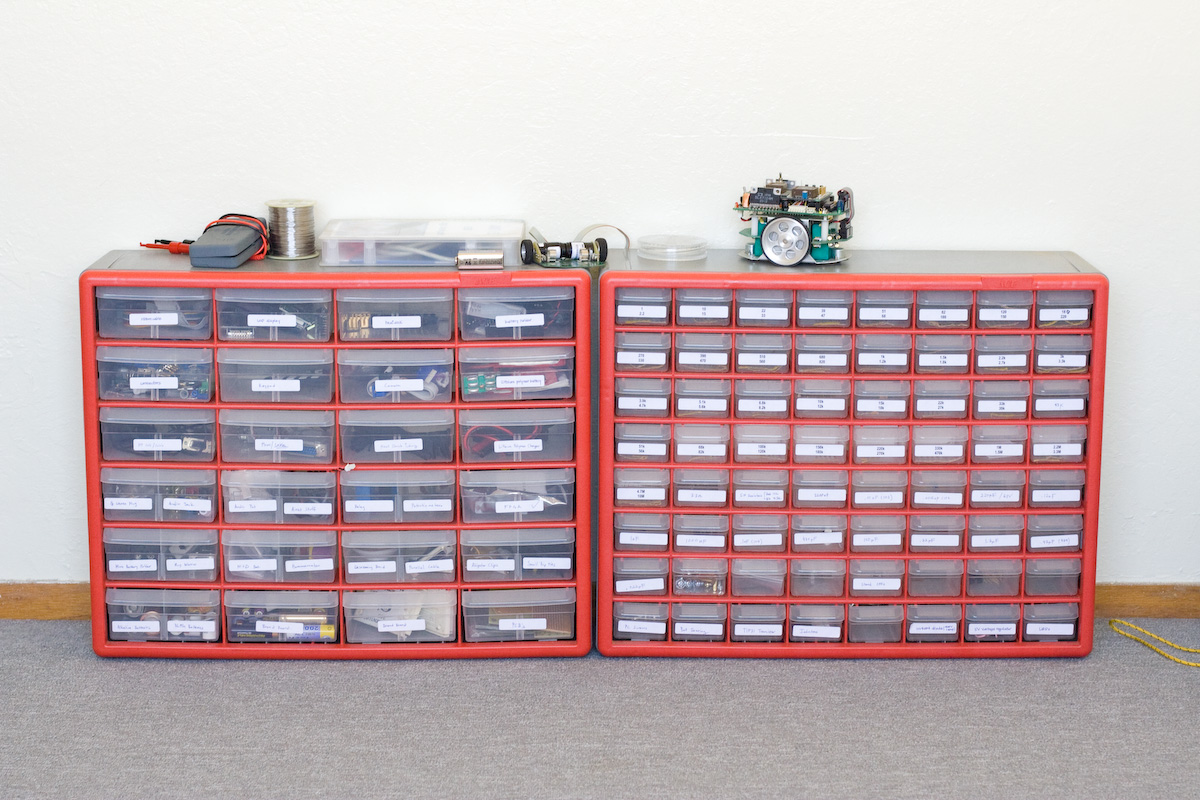
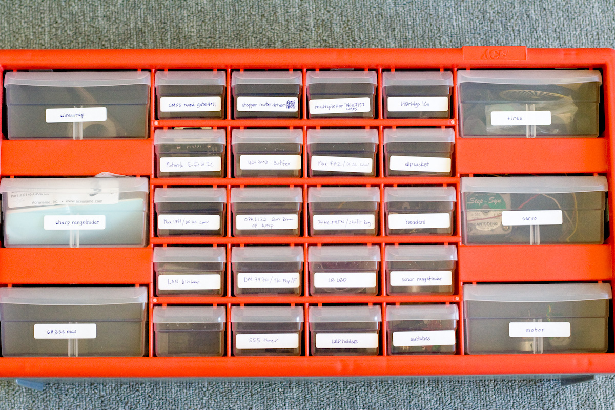
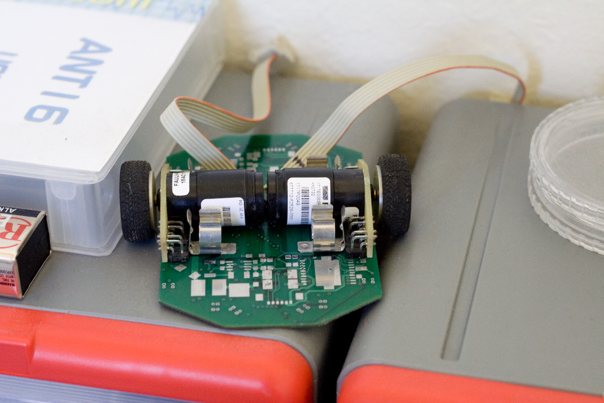
Some of the more notable parts of the collection:
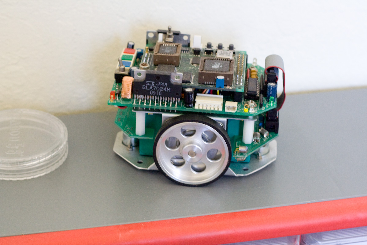
- An AIRat2 maze-solving robot. This apparently sells for $400 new! But this one is missing its LCD panel, and I don’t have the software for it. Still, I bet I can get it doing something interesting.
- A second half-built robot, with a couple of geared motors.
- A servo and a stepper motor (I think).
- Assorted robot tires.
- Two sonar rangefinders.
- A Sharp rangefinder (IR based?)
- A Xilinx CPLD development board.
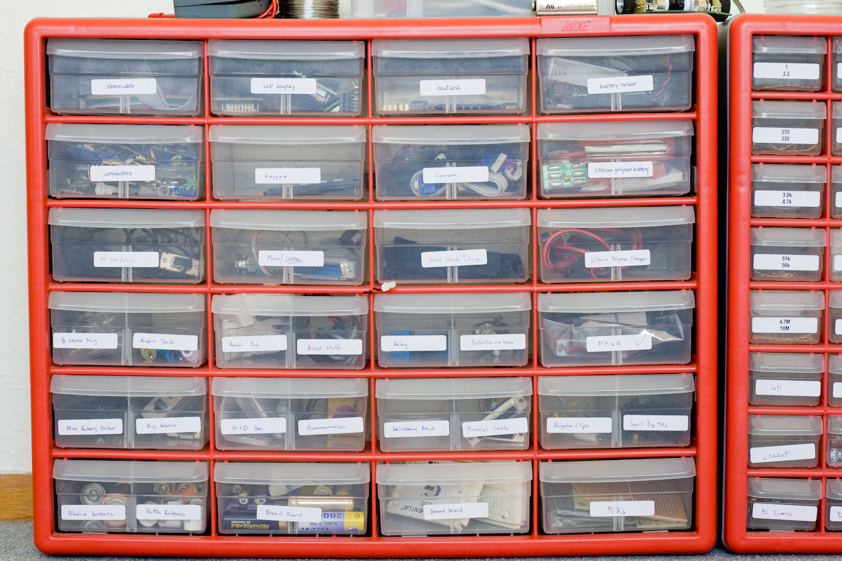
- Some kind of camera and interface board.
- Four 11 volt lithium-polymer battery packs, and a LiPo charger.
- Tons of NiMH and NiCd rechargables.
- A 12 volt, 1 amp power supply.
- A solar panel.
- Lots of protoboards.
- Four LCD text displays.
- Assorted ICs: op-amps, voltage regulators, 555 timers, and more.
- A pile of IR and visible LEDs.
- A “helping hands” tool.
- A very nice wire cutter/stripper tool.
- A zillion feet of wire of various gauges and types.
- A lifetime supply of resistors, capacitors, diodes, transistors, relays, pots, switches, headers, etc.
That’s a ton of stuff! Hopefully I’ll get a chance to use it all well. Some of the parts like the batteries, CPLD, and passive components I can definitely use, but others like the robot or the sonar rangefinder will require a decent investment of time to investigate.
Read 7 comments and join the conversationWire Wrapping Pain
I’m beginning to really hate wire-wrapping. Sure, it’s easy to make modifications to the wiring, and the finished result will be nice and sturdy, but it’s SO SLOW to build! Now that my board is getting pretty full, it’s hard to even see the pin numbers, and I have to hunt around to find the endpoints of each wire. And especially when I need a length of wire that I don’t already have pre-cut, I have to spend more time measuring, cutting, and stripping. All told, I’m averaging a couple of minutes per wire. After about an hour of wire-wrapping, my brain overdoses on connections from AG32 to BB08, I begin to feel dizzy, and I have to stop. This has been my first wire-wrapping project, and I think it will be my last.
What then, if not wire-wrapping? A solderless protoboard is nice for prototyping, but doesn’t work well for large designs. It’s also not very permanent, since it’s easy to accidentally knock a wire loose. I could hand-solder point-to-point wires on a breadboard, but I think that would be like wire-wrapping, only worse. For medium-large designs like BMOW, I think the only real alternative is custom printed circuit boards. Unfortunately custom manufactured PCBs are expensive, at $50 to $100 depending on the size and quality. They’re also difficult to modify if you discover an error, so you’ll probably need to go through several versions of the PCB before you get something that works. Some people have had good success making their own PCBs at home, but it involves some nasty chemicals and drilling lots of holes and other headaches I’d rather avoid.
I did some comparison shopping for a hypothetical 4×6 inch 2-layer custom PCB:
Futurlec: $41 for a single plain board. $77 with soldermask and silkscreen.
BatchPCB: $70, including soldermask and silkscreen. Long lead times.
ExpressPCB: about $70, no soldermask or silkscreen.
Most places have a fairly high setup cost, but low cost for bigger boards, or higher quantities of boards. For example, Golden Phoenix will make a 100 square inch board with soldermask and silkscren for $89, and a 155 square inch board for $99.
Read 3 comments and join the conversationRobo-Flower
I recently took a break from BMOW’s multi-tasking support to work on something completely different. (Actually, I have a multi-tasking demo working in the simultator, but it doesn’t work on the real hardware yet.) The “something different” was a robo-flower: a pulsing light powered from solar energy that’s made to look like a flower from Junkyard Wars. The circuit was based on this Make Magazine article, but the construction design is my own. Here’s a photo of the result:
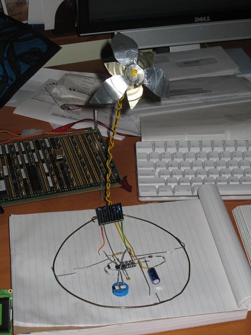
During the day, the solar cell charges the main storage capacitor. At night, the storage capacitor powers the circuit, making the LED in the flower’s center pulse organically every few seconds. I followed the circuit design from the Make article, with these exceptions:
- Replaced the 1000uF “pumm” capacitor (C3) with a 3300uF one. This was one of the suggested alterations.
- Replaced the rechargable battery with a 1F “super capacitor”. A 10F capacitor was a suggested alteration, but I couldn’t find one.
- Where their diagram shows resistor R3 connected to the positive power supply, I instead connected it through a diode to the negative end of the LED. This makes the LED turn off all the way at the end of each pumm, which I think looks better.
The robo-flower works, but I’m pretty disappointed with how it turned out. For one thing, the pulses of light are surprisingly dim, compared to what I’d expected. They reach a brightness I’d call “on”, but not bright. If you look at the circuit diagram, you’ll see that the pulses come from the 3300uF capacitor (charged to about 3v) discharging through an LED. With no current-limiting resistor, there should be a brief pulse of high current = high brightness, but that’s not what I’m seeing.
The bigger disappointment is that even after leaving the flower in the sun until the main 1F storage capacitor is fully charged (as measured with a voltmeter), the pulsing only lasts for about 15 minutes after the sun’s illumination is lost. That’s pretty lame. Other designs that use rechargable batteries pulse nearly all night, I think, so I was expecting much more. Yes, it’s a capacitor powering the circuit and not a battery, but 1F is a mighty-big capacitance.
If I get motivated enough, I may build another copy of the circuit on a protoboard, so I can experiment with it further, or measure the voltage at various points on the oscilloscope, to see if I can’t improve the behavior. Otherwise it’ll be one more piece of odd electronics junk littering my home. 🙂
Be the first to comment!Digital Memories
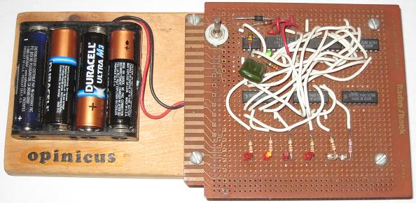
While hunting for my soldering iron, I found my first digital electronics project gathering dust in a box. I thought I’d thrown it out long ago, so I was happily surprised to see it. It’s not much to look at– just a 555 timer and a bunch of NAND gates wired to a row of LEDs, configured so that a single “blip” of light races up and down the row like Knight Rider’s front bumper. In fact Knight Rider was probably still on the air when I built this thing in the spring of 1991. I called it The Opinicus Blinker.
Opinicus was the name of a fake technology company I pretended to work for during high school, so that I could get into trade shows and scam real companies for product samples.
Sadly, The Blinker broke a long time ago, which is why I thought I’d tossed it out. I hoped maybe I could troubleshoot the problem and fix it, but after cleaning the battery contacts and installing a new set of batteries, it fired right up. Woohoo! There it is with the second LED from the left illuminated. Not bad for a 17 year old piece of junk. And check out the legend on those chips: “SOVTEK 7400 11/88, MADE IN USSR”. Wow.
The rate of progress on BMOW has been slowing, as I prepare to begin actual construction. Everything is pretty much ready to go, and there are just a few more parts I need. The last real hurdle is working out the physical layout of the machine: where to fit the chips on the board, where to fit the board in the case, how to connect power, and so on. I’ve decided to mount everything on a piece of wooden shelving for the time being, rather than build a real case. I didn’t want to get so hung up on case design that it distracted me from the main task of getting the CPU built and running.
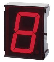
Read 2 comments and join the conversation7 Segment LED
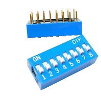
Here’s a job that sounds reasonable enough: connect an 8-wide dip switch to a pair of 7 segment LED displays, so that the 8-bit binary number on the dip switch is displayed as a 2-digit hex number on the LED displays. I didn’t think it would take me too long to configure a GAL to control which segments of the LED displays to turn on, and then wire the whole thing up. Boy, was I wrong.
My basic plan was to connect the dip switch to the GAL’s inputs, and the LED displays to the GAL’s outputs. Easy cheesy.
Problem 1. A dip switch doesn’t provide logical 0 or 1 values (0 or +5 volts) that can be connected right to the GAL’s inputs. It’s just 8 switches, each one either open or closed. A simple pull-up resistor circuit is needed to generate a 0 or +5 volt input from the switch position. When the switch is open, no current flows through the resistor, so there’s no voltage drop, and the output terminal is at +5 volts. When the switch is closed, the output terminal is tied directly to ground (0 volts).
One problem with this design is that when the switch is closed, current is constantly flowing from +5 through the resistor to ground. With a 440 Ohm resistor (the largest I had on hand), 11 milliamps (5 / 440) flows through the resistor. With all eight switches closed, that’s 88 mA wasted. My hack-tastic power supply can probably only supply a few hundred milliamps, so that’s a big fraction of the total available supply.
Problem 10. Decoding a 4-bit number is fairly simple: 4 inputs from the dip, the GAL decodes the data, 7 outputs to the LED display. An 8-bit number using the same approach would require 8 inputs and 14 outputs, but the GAL only has 10 outputs. Doh!
My solution is to share the same 7 outputs between two different LED displays, with an 8th and 9th output to enable one or the other display. Only one display can be illuminated at a time, but if you switch between the displays rapidly enough, it looks as if they’re both illuminated. I used a 1 MHz clock oscillator to switch back and forth between the two displays. The 7 data outputs from the GAL are connected to the positive terminal of the 7 LED segments on each display. The 8th data output is connected to the shared negative terminal of the LED segments in the first display, and the 9th data output is connected to the shared negative terminal of the second display.
To illuminate a display, its shared negative terminal is set to 0, and the appropriate data outputs are set to 1, generating a positive voltage across the LED segments. To deactivate a display, its shared negative terminal is set to a high-impedance (disconnected state), so none of the LED segments will light up regardless of what the data outputs are doing. It would also be possible to deactivate a display by setting its shared negative terminal to 1 (+5 volts), but this would put a reverse voltage across the LED segments. That’s best to avoid, since too large of a reverse voltage can damage a diode.
Problem 11. Writing the logic equations for the GAL to decode 8 input bits into 2*7 LED segments proved more difficult than I expected. My first attempt had way too many product terms per output, and was too complex to fit in the GAL. I did some hand optimization, but it was tedious and error-prone. Finally I found a website with an interactive Java applet for making Karnaugh maps, and used it to simplify the equations enough to fit the GAL. The Java app was nearly as tedious as hand optimization, though, and it took me a long time to finish the simplification.
Problem 100. You can’t just connect a chip’s output pin directly to an LED. Since the diode offers nearly zero resistance, it would be like shorting the power supply to ground if the output pin’s value were a logic 1. Instead, a resistor must be put in series with the LED, to limit the current. Larger resistances will limit the current more, but will also diminish the LED’s brightness. I used 220 Ohm resistors in series with each LED segment, which should result in a current of 23 mA (5 / 220). Most LED’s appear designed to hit their advertised brightness level at about 10-20 mA.
Problem 101. There are a lot of wires to connect! OK, this isn’t really a problem, but I was still surprised at how many wires I needed to cut, strip, and push into the protoboard for such a simple project. 8 from the power supply to the 440 Ohm resistors, 8 from the resistors to the dip switch, 8 from the dip switch to the GAL, 7 from the GAL to the 220 Ohm resistors, 14 from those resistors to the two 7 segment displays, plus the 2 shared negative terminal connections, the 1 MHz oscillator, and a handful of other miscellaneous wires. Ugh.
Problem 110. After I’d finished everything and turned on the power, it didn’t come even remotely close to working. LED segments light up in totally random ways. The same dip settings didn’t even always generate the same results. Changing the MSB of the input changed which display was illuminated. Even just touching the circuit with my hand sometimes caused things to change. I was totally confused. At first I thought maybe I was drawing too much power from my power supply, and the voltage levels were getting out of spec, causing erroneous behavior in the GAL. A lot of poking and probing with a multimeter suggested everything was OK in the voltage department. Then I hunted for wiring errors, but found none. I rechecked all my logic equations as well.
After a very long time, I discovered that the GAL had been misprogrammed somehow, and some of the outputs were using the clock input as if it were a data input. I have no idea how that happened– is the chip failing? Is my chip programmer faulty? Sun spots? I reprogrammed the GAL, and things started working much better. It was still broken, but at least now it was broken in a deterministic way, and it sometimes displayed recognizable digits on the LED displays.
Eventually I discovered several errors in my logic equations that I’d overlooked the first ten times. In one place I’d used an AND instead of an OR, and in another I’d omitted an entire term from the equation. It’s amazing how many times I looked at those equations without seeing the mistakes.
After fixing those, the whole thing was almost working, except for:
Problem 111. Strange things happen with long (and not so long) wires involving cross-talk and noise. I never did satisfactorily explain how the MSB of the data input seemed to be acting like a clock input. When I wired the clock input pin straight to ground, the GAL would still often appear to have been clocked (the active LED display would switch) when I changed the MSB. The problem went away when I used a shorter wire to connect the clock pin to ground, so I suspect it was some kind of cross-talk from the neighboring wire. When I later connected the clock pin to the 1 MHz oscillator, it seemed to work fine.
The disconcerting thing is that the clock wire was not especially long (3 inches) nor close to the MSB wire, except that they happened to connect to adjacent pins on the GAL. If it’s truly that easy to accidentally perform false clocking, then I’m going to have a lot of problems building the full machine.
Problem 1000. Everything was finally working, but I wanted to examine the circuit behavior in more detail. Earlier I mentioned the 220 Ohm resistors I put in series with the LEDs, which should have resulted in a 23 mA current through each LED. I measured the current, and it was only about 6 mA. I also measured the voltage at the GAL’s data output pins, and rather than +5 volts, it was only 3.2 volts. This suggests a problem.
I can’t explain why I saw 6 mA of current specifically, but after reading the GAL datasheet more carefully, I decided I was lucky (?) to get even that much. The chip’s maximum output current per pin at a high (logic 1) output voltage is only 3.2 mA. Exceeding that by nearly 2X explains why the output voltage was dragged down from 5 to 3.2 volts. It’s possible that could damage the chip. At the very least, it doesn’t seem like a good design. I’m still curious why I saw 6 mA and not 3.2 or 23, though. Maybe I reached the maximum amount of current that my power supply can deliver, or maybe the diode itself has some current limiting effect?
The math tells me a 1562 Ohm resistor in parallel with the LED would give me the maximum rated current of 3.2 mA per LED segment. Would that be enough current to get sufficient brightness, though?
Although I didn’t measure it, I think I’m running into similar problems with the shared negative terminal of the LEDs, which is also connected to a GAL output pin. The datasheet says the max current per pin at a low (logic 0) output voltage is 16 mA. If I’m sending 6 mA per LED segment through seven segments with a shared negative terminal, then that’s 42 mA (6 * 7), way more than the rated maximum.
Problem 1001. Now I have something that works, but feels iffy. I wouldn’t incorporate it into a finished computer design, due to concerns about greatly exceeding the GAL’s rated maximum output current. The trouble is, I’m not sure how to fix it without introducing more parts between the GAL and the LEDs to provide and regulate current. I’ve seen ready-made LED driver chips, but they’re always binary coded decimal rather than hex. Whatever the ultimate solution, it feels like an awful lot of work just to display a single byte on a pair of LED displays.
To put a positive spin on this experience, I learned more about the kinds of difficulties and pitfalls I’m likely to encounter when I begin to build the machine on the wire wrap board. It’s much better to face them here on the protoboard, where alternative solutions are easy to try, than on the more unforgiving wire wrap board.
Be the first to comment!