

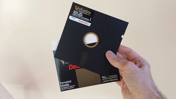
Archive for the 'Floppy Emu' Category
5.25 Inch Disk Firmware
The updated Apple II firmware for Floppy Emu is now available! This update adds 5.25 inch 140K disk image support, and is compatible with any Apple II model, using the standard Floppy Emu hardware. Download apple-II-0.1C-F3 and try it out! I also included a few sample disk images, so you can be running Oregon Trail and a few other classics right away. The firmware supports standard Apple II 140K disk images in .PO, .DO, .DSK, .NIB, or .2MG formats, as well as Apple II 800K (3.5 inch) disk images in .2MG or Disk Copy 4.2 formats. Press the SELECT button from the Emu title screen to switch between 5.25 inch and 3.5 inch disk emulation modes.
Some important notes:
- I’m having difficulty with 5.25 inch disk write emulation, so this firmware treats 5.25 disk images as read-only. I hope to add full read/write support for 5.25 inch disks in another firmware release soon.
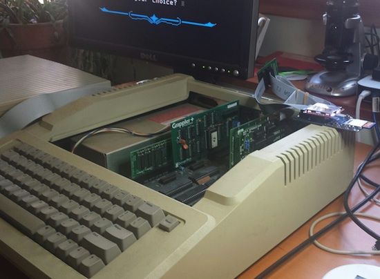
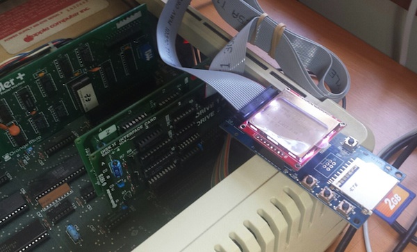
- The Floppy Emu board can be connected directly to the 19-pin floppy connector on the Apple IIgs or Apple IIc. For the Apple II, II+, and IIe, the Emu board should be connected to your disk controller card: either the Disk 5.25 Controller Card with 19-pin connector, or the classic Disk II Controller Card with two 20-pin connectors. If using the Disk II Controller Card, be careful to orient the cable correctly, since the card’s connector is not keyed and it’s easy to accidentally connect the cable offset or backwards. The red stripe on the cable should go to the pin marked “1” on the Disk II Controller Card.
- This firmware includes support for 5.25 inch and 3.5 inch Apple II disk emulation. 5.25 inch disk emulation works on a stock Emu board, and does not require any adapter. Full emulation of 3.5 inch disks requires an adapter board that I plan to release soon. Without the adapter board, 3.5 inch disk emulation works on a ROM 01 Apple IIgs when booting from the Floppy Emu, but not on a ROM 03 IIgs or when the Emu is not the boot disk.
- As with the earlier Apple II firmware versions, use this firmware only when connected to an Apple II computer. If a Floppy Emu board running the Apple II firmware is connected to a Mac or Lisa, it could cause damage.
NIB Images
This firmware introduces support for NIB images, which contain the raw disk bytes stored on a physical floppy disk, instead of the high-level sector data contained in other types of disk images. With NIB images it’s possible to store and emulate many types of copy-protected disks, including disks with non-standard sector headers, custom sector sizes and encoding, and all sorts of other crazy schemes. This is important for the Apple II world, because the use of disk-based copy protection was common among Apple II software. A disk emulator that didn’t support NIB would be limited to only using “cracked” versions of the software in which the copy protection had been removed.
Implementing robust NIB support is challenging. I’m not sure if other Apple II disk emulators also support NIB format, but at least one that I checked does not, so I’m happy that I was able to make it work for Floppy Emu. After digging into the details, I can understand why some designers may have chosen to skip NIB. The NIB format represents a track as 6656 disk bytes, but this is insufficient to represent the full structure of a real floppy disk track. On a real floppy, most disk bytes contain 8 bits, but some disk bytes called sync bytes are actually 10 bits long. Of course a 10-bit quantity isn’t a true byte, but the term “sync byte” is used regardless. The sync bytes are FF (hex) followed by two zero bits, so in binary they look like 1111111100. The problem is that sync bytes are stored in the NIB file as plain 8-bit FF bytes, and the knowledge that a particular FF is a sync byte instead of a standard FF data byte is lost.
I believe the NIB format was developed mainly for use with PC-based Apple II emulators, and not for use with real Apple II hardware. While I’ve never investigated how emulators like AppleWin are designed, I would guess it’s impossible for the emulated disk controller to get out of sync with the emulated disk, so the absence of proper sync bytes in the NIB data is unimportant. But when running on real Apple II hardware, such as with the latest Floppy Emu firmware, the absence of sync bytes is fatal. To solve this problem, I’ve designed the firmware to make an educated guess as to which FF bytes in the NIB are actually sync bytes, and which are just plain data bytes. In practice, this seems to work great most of the time, but copy protection schemes are often designed to intentionally thwart exactly this kind of analysis. In my tests, all the copy-protected NIB images that I tried worked, save for one intermittent problem with Moon Patrol on the Apple IIgs. Yet the Moon Patrol NIB worked fine on my Apple IIe, so maybe it’s some kind of IIgs incompatibility rather than a NIB issue.
Write Support
Support for writing to emulated 5.25 inch disks has proven to be much more troublesome than I’d expected. Single-sector writes appear to be working fine: I can use a sector editor tool to view and modify individual sectors on the emulated disk, and the data gets modified correctly. That means there aren’t any low-level problems involving timing or checksums, which is great. Yet when I try a higher-level write operation, such as copying a file, everything blows up. The exact nature of “blows up” is hard to identify – if I could explain it, I could probably understand how to fix it. In practice it means that the software complains about “write error”, or the Emu displays a buffering-related error.
On the Macintosh, all floppy disk write operations are verified by reading back the newly-written data, unless verification is explicitly disabled. From the point of view of a disk emulator designer, that’s a very nice feature, because any mistakes that occur during writing are caught and reported right away. But for Apple II software, verification of writes doesn’t appear to be the norm. At least in the GS/OS Finder, you can duplicate a file on a floppy disk, and GS/OS will show that everything succeeded regardless of what was actually written to the disk. If there was a problem, you’ll only find out about it later when you try to use the new file.
A second wrinkle is that some Apple II copy software like Copy II+ does something more akin to a single-track format operation than a standard write. The sectors on a disk consist of an address header followed by a data chunk. Normally the address headers are written once when the disk is formatted, and then never touched again – only the data chunks are modified. My experiments show that Copy II+ violates this rule, though, and writes new address headers. Floppy Emu isn’t designed to handle this, so the write operation fails. This isn’t an Apple II issue, but is also true of the Mac and Lisa firmware, and has been the case since the earliest days of Floppy Emu. There may be a way to configure Copy II+ so it doesn’t rewrite the address headers, but if so I haven’t found it yet.
I found more unexpected results when snooping on ProDOS disk writes. ProDOS works in units of 512 byte blocks, which are stored as two separate 256 byte sectors on the floppy disk. Every ProDOS write should therefore look like two successive sector writes, to two different physical sectors. But what I observed was that the same physical sector was written twice in a row. This must be a bug somewhere in my layers and layers of abstractions, but I haven’t been able to locate it. Or maybe the way I’m tracking the write activity is flawed.
In short, write support is a pain. I can see when something went wrong by observing error messages, but I only have a limited ability to look inside and examine each step of the write process to find the cause. I may need to invest some time in creating better debugging tools, before I can get to the bottom of it all.
Feedback
As always, I welcome your feedback. If you’ve tried this new 5.25 inch disk emulation on your Apple II system, leave me a note in the comments! Even if you have nothing to say beyond “works on my IIc”, that’s still helpful to know. Thanks!
Read 9 comments and join the conversationFloppy Emu Has Cholera
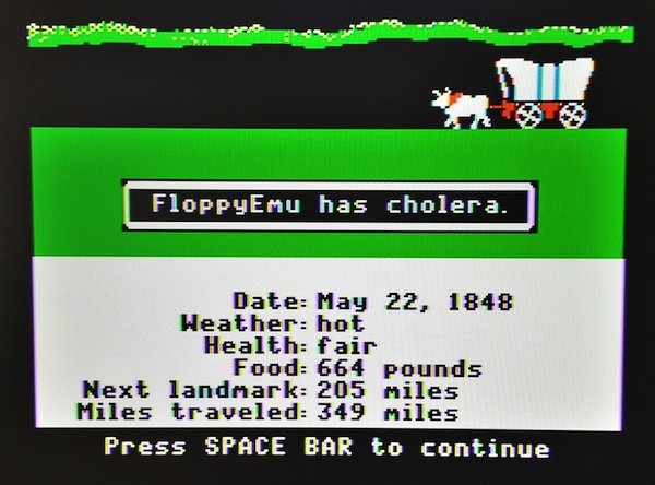
Achievement unlocked! 5.25 inch 140K disk emulation for Apple II is now working for Floppy Emu. I booted up my Apple IIe with an Oregon Trail disk image, lost some oxen, got cholera, and died. The 5.25 inch disk emulation has been tested on a IIgs with the built-in floppy port, on a IIe with the 19-pin Disk 5.25 controller card, and on a IIe with the classic Disk II controller card. Awesome!
This brings the total number of disk formats that Floppy Emu can emulate to eight: Mac 400K, Mac 800K, Mac 1.44MB, Mac hard drive (HD20 compatible), Lisa 400K, Lisa 800K, Apple II 800K (3.5 inch), and Apple II 140K (5.25 inch).
These are early days for the 5.25 inch Apple II disk emulation, so I won’t be posting the new firmware quite yet. There are still a number of issues remaining that I hope to resolve soon. The big one is write support: the current firmware doesn’t yet implement 5.25 inch write emulation, so disks are read-only. The disk image format support also isn’t complete, and raw DOS 3.3 order images (.do files) are the only format that works. I expect to add ProDOS order (.po files) and 140K 2MG images soon – or is 2MG only used for 800K disk images? I’ll have to check.
In my previous post, I mentioned that the raw disk bytes weren’t always being received correctly by the Apple II. It turned out that the width of my “1” pulse was too narrow, and sometimes a 1 would be detected as a 0. Data arrives from the disk at a rate of 4 microseconds per bit, where a logical 0 is sent as 4 microseconds of 0 volts, and a logical 1 is sent as a short pulse to 5V and back within a 4 microsecond window that’s otherwise 0 volts. Initially the width of my pulse was 0.25 microseconds. When I widened it to 0.75 microseconds, it started working reliably. That’s curious – is the disk controller actually doing polling, instead of edge triggering? Why didn’t the narrower pulse work?
It was a headache getting the checksum algorithm working correctly. The checksum is described in the book Beneath Apple DOS, but even after re-reading it several times, I was still confused. The algorithm is tightly coupled to the method the Apple II uses to read and write disk data, where it performs a process called “pre-nibbilization” before writing each sector, separating the upper and lower bits of each data byte and storing them in two different buffers. Floppy Emu works differently, performing nibbilization on the fly, so it was somewhat awkward to transmit data and checksums the same way.
Interleave and Sector Ordering
The other question that I struggled with was sector ordering. If you’ve been around the Apple II emulation world for a while, you’ve probably heard the terms “DOS order” and “ProDOS order” when referring to disk images. You may have also seen some discussion of sector interleaving within a track. The meaning of these terms and the interplay between them took me quite a while to understand.
Some background: each sector on the disk is prefaced with a sector header. The header is not part of the sector itself, and doesn’t count as “data” when you’re totalling up how much data a disk contains. A crucial piece of information contained in the header is the sector number, used by the operating system to identify which sector is which. Typically the sectors aren’t actually stored consecutively on the floppy disk, but are interleaved. A Macintosh 800K floppy track has the sectors interleaved like this:
0 6 1 7 2 8 3 9 4 10 5 11
This is a performance optimization. The floppy disk is always spinning, and without interleaving, a vintage computer would be too slow to finish processing the data from sector 0 before sector 1 spun under the head. By the time it was ready to begin reading sector 1, that sector would have already spun past, so the computer would have to wait for it to spin all the way around again. By staggering the sectors on the floppy disk, the computer gains some extra breathing room and avoids needing a full rotation for the next sector.
Things begin to get confusing when we talk about physical sectors vs logical sectors. Physical sector numbers are the numbers contained in the sector headers on the disk. Logical sector numbers are determined by the OS, and define the data contained in each sector. If you stored a large text file on a floppy disk, the first few sentences would be stored in logical sector 0, the next few in logical sector 1, then logical sector 2, etc.
On the Mac, physical and logical sector numbers are the same. The sector number in the sector header is the same as the number assigned by the Mac OS. If we use A[B] to describe a sector whose sector header number is A and whose data contents are the operating system’s sector number B, then the Mac has a 1:1 relationship:
0[0] 6[6] 1[1] 7[7] 2[2] 8[8] 3[3] 9[9] 4[4] 10[10] 5[5] 11[11]
The Apple II handles interleaving differently. Physical sector numbers aren’t interleaved, and instead they’re just numbered consecutively 1 to N along the track. But the operating system uses so-called “software skewing”, where logical sector N is not necessarily stored in physical sector N. For DOS 3.3, the relationship looks like this:
0[0] 1[7] 2[15] 3[6] 4[14] 5[5] 6[12] 7[4] 8[11] 9[3] 10[10] 11[2] 12[9] 13[1] 14[8] 15[15]
So when a DOS 3.3 Apple II program wants sector 4, it actually fetches physical sector 7 from the floppy disk. For all practical purposes, physical sector 7 is sector 4. My head hurts already.
With ProDOS, logical data is stored in 512 byte blocks instead of 256 byte sectors. Each 512 byte ProDOS block N is stored in two separate 256 byte physical sectors, NA and NB:
0[0A] 1[4A] 2[0B] 3[4B] 4[1A] 5[5A] 6[1B] 7[5B] 8[2A] 9[6A] 10[2B] 11[6B] 12[3A] 13[7A] 14[3B] 15[7B]
Confused yet? A DOS ordered disk image is one in which the physical sectors are stored in ascending order by DOS 3.3 logical sector number. A ProDOS ordered disk image is one in which the physical sectors are stored in ascending order by ProDOS logical block number. While the two orderings are obviously derived from the two different operating systems, they are ultimately just arbitrary ways of grouping data into 256 byte chunks. DOS 3.3 software can be stored in ProDOS ordered disk images, and vice-versa.
5.25 Inch Disk Kickoff
I’ve started working on Apple II 5.25 inch disk emulation for Floppy Emu. It’s still early, and it’s progressing more slowly than I expected, but I think it’ll work. It will be great to have a new mode to emulate the zillions of 5.25 inch Apple II disks out there. I’ve been using the IIgs for my testing, but it should work on any Apple II series machine. No adapters needed either – just plug in the Emu board and go.
The first step was to convince the computer that there was even a 5.25 inch drive connected. That took more effort than I expected, because the 5.25 drive doesn’t have any way of directly telling the computer “I’m here”. After some trial and error, I discovered that the computer just blindly turns on the drive motor and starts reading from it. If it gets valid data or garbage data, either way it knows there’s a drive attached, but if it gets no data at all then it assumes no drive is present. I had assumed an empty drive would send no data, but some investigations with a logic analyzer proved that theory wrong. To make Floppy Emu be detected as an installed drive, I had to change the firmware to send a constant stream of sync bytes even when there’s no disk inserted.
Stepping the drive head to the correct track proved to be a major hassle. The Apple II directly controls a 4-phase stepper motor in the 5.25 disk drive, activating each coil in the correct sequence to move the stepper in or out. I modified the firmware to monitor these control signals, and simulate what would happen to a real stepper motor. This was more difficult than it might sound, because the control signals can be driven in various ways to produce half steps, full steps, or weird combinations of inputs that don’t do anything well-defined. Fortunately I think I’ve got it working now.
Speaking of the stepper controls, I hooked up my logic analyzer to the disk interface signals so I could see what was going on. For all the years I’ve been working on floppy emulation, I can’t believe I’ve never done this before! I normally rely on indirect methods of observation, from the computer or the Emu, and haven’t had a direct window onto the actual disk signals.
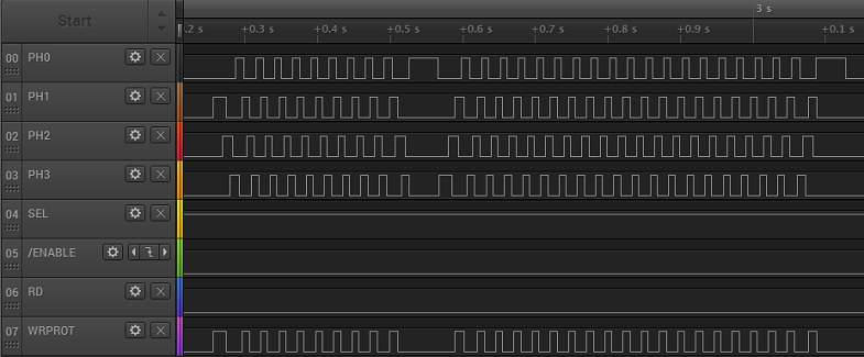
The waveform above shows the characteristic chukka-chukka-chukka of an Apple II 5.25 inch drive when the computer recalibrates the track position. During the first section, the phase lines are repeatedly activated one at a time in order, from lowest to highest, which moves the drive head outwards. Then there’s a pause, followed by a second section where the phase lines are activated from highest to lowest, which moves the drive head inward. Eventually the head hits a mechanical stop at track 0, making the familiar rattling sound of a 5.25 inch floppy drive.
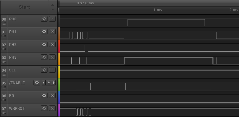
For comparison, the waveform below shows what happens on the IIgs, just a brief moment after the power is turned on. Note that the time scale is much smaller, and the phase lines aren’t driven in sequence, but instead each one has an independent behavior. I believe this is the IIgs asking “Hello, are you a SmartPort hard disk? No? OK then.” I’ll find out more when I look further into SmartPort HD emulation.
Copy II Plus, an Apple II disk copy program, has some very nice sector and track diagnostic tools built in. Using these I was able to verify that my track stepping logic is working. I was also able to capture a raw dump of an entire track, showing all the bytes straight off the disk (or the Emu), without any kind of post-processing to try to identify where the sectors are. This will be incredibly valuable as I start to work on actually sending the correct disk data.
In the image below, you can see that it’s already sort of working. This shows a Copy II Plus dump of track 0 of an emulated 5.25 inch disk from Floppy Emu. The data itself is actually from a Macintosh disk, with Macintosh style sector headers, so that part obviously isn’t right. But what’s encouraging is that the raw data is being received correctly by the Apple II – I circled the familiar D5 AA 96 that marks the start of a sector, and D5 AA AD that marks the start of the sector’s data payload.
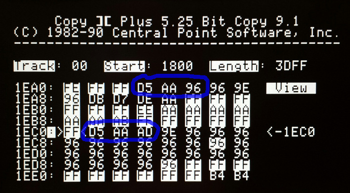
Unfortunately, some of the data is received incorrectly. The screenshot shows an example that mostly worked, but in many cases, parts of the sector are garbled. The data payload shown above should have contained hundreds of “96” bytes after the D5 AA AD, but it only has 23 of them before something goes wrong. Even the highlighted “FF” sync bytes before the data payload are wrong: some of them show “AA” and other incorrect values. Maybe the bit rate is slightly off? Bad voltage levels? Microcontroller interrupts messing with the bit timing? I’ll figure it out eventually.
Read 3 comments and join the conversationROM 03 Revisited
Good news, Apple II fans! The Apple IIgs ROM 03 mystery has been solved. A few weeks ago I added new support to Floppy Emu, for emulation of 3.5 inch Apple II disks. I used it to boot my Apple IIgs with GS/OS… fun. Then I started hearing from other IIgs owners for whom the new firmware didn’t work, but I couldn’t understand why… not fun. The issue seemed related to differences between IIgs version ROM 01 and ROM 03, but I wasn’t sure what was going on or how to fix it. This prompted the post Apple IIgs ROM 03 Headaches. Now, after a lot of head scratching, I think I’ve finally got it figured out.
A huge “thank you” goes to Steve Palm, who did an extraordinary amount of testing under different conditions with his ROM 03 machine, and to Jason Galarneau, who loaned me a ROM 03 machine to experiment with directly. What I learned was that the ROM 03 problem is caused by incomplete decoding of the disk drive enable signals, causing the Emu to respond at inappropriate times. I had actually diagnosed the problem correctly in this earlier post, and I even provided a potential solution there, but I somehow convinced myself this wasn’t the ROM 03 problem, or wasn’t the main problem. Wrong!
On a Macintosh floppy port, there’s a single active low signal called /ENABLE that tells the drive when to wake up. The earliest Apple II 5.25 inch drives worked the same way. But Apple later complicated things in order to support daisy chained disk drives, and chains containing multiple different types of drives, to where on an Apple IIgs the floppy port has three different enable signals: /DRIVE1, /DRIVE2, and /EN3.5. Floppy Emu was only listening to /DRIVE1, and wasn’t even connected to the other signals. The difficulties are described in much more detail in the earlier post, so I won’t repeat them here.
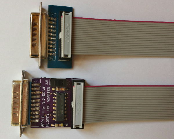
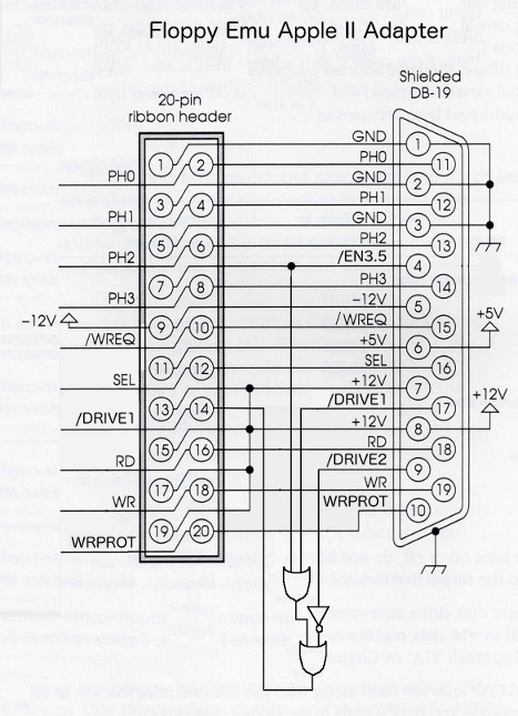
The final step was to build a prototype of the external adapter described in the earlier post. Since the Emu board lacks connections for /DRIVE2 and /EN3.5, the external adapter is responsible for decoding those signals along with /DRIVE1, and passing the result to Floppy Emu as a single /ENABLE signal. And what do you know, it works! No more ROM 03 problems, and no more limitations on where the Emu can appear in the disk daisy chain.
The adapter prototype also includes a couple of resistors not shown in the diagram. There’s a 10K pull-up resistor for /DRIVE2, because that signal isn’t connected on a Mac or Lisa. And there’s a 470 ohm series resistor on WRPROT, which is the only signal that changes direction between the Mac/Lisa and Apple II firmwares. No more worries about possibly damaging something if you accidentally use the Apple II firmware while connected to a Mac.
A Universal Apple Adapter for Floppy Emu
The original name I gave the adapter is misleading – it’s not an adapter for the Apple II, it’s an adapter for everything including the Apple II! There’s a photo of the adapter prototype at the top of this post, with the current do-nothing adapter also pictured for comparison. The new universal adapter has a switch on it. Set it to “3.5” if you want to emulate an Apple Disk 3.5 for Apple II, or set it to “OFF” if you want to emulate any other type of Apple II, Mac, or Lisa disk.
There’s potential for confusion with this new universal adapter, so I’m trying to choose names and terminology carefully. The adapter is only REQUIRED in a few specific circumstances, but it’s COMPATIBLE with all circumstances, so you can just plug it in and leave it there. Macintosh computers and the Lisa don’t need the adapter, and you can also boot an Apple IIgs ROM 01 machine from the Emu without the adapter. And when Apple II 5.25 inch and SmartPort disk emulation is ready, those shouldn’t need the adapter either. But for 3.5 inch emulation on a IIgs ROM 03 machine, or 3.5 inch emulation on a IIgs ROM 01 machine where the Emu is not the boot disk, this adapter is just what the doctor ordered.
So what’s next? I hope to have some of these adapters available for sale shortly. They’ll be offered as an alternative to the existing “convertible extension cable”, for a few dollars more. People who expect to use Apple II 3.5 inch disk emulation (mainly IIgs owners) along with other emulation modes can use the new cable, while people who don’t care about Apple II 3.5 inch disk emulation can stick with the current cable. Longer term, I hope to build the functionality of the universal adapter into a new Floppy Emu, but that won’t be any time soon.
Crazy idea: with other external adapter boards like this one, with a different external connector, it might be possible to develop Floppy Emu disk emulation firmware for completely different computer platforms. Atari disk emulation, anybody? Amiga? They all operate on the same basic principles as the existing Floppy Emu disk emulation. Yes, there are many differences in the details, but the more emulation modes I implement the better I’m getting at abstracting the drive-specific parts from the shared functionality. Maybe someday…
Read 8 comments and join the conversationCircuit Protection: Economics and Electronics
Remember this problem that I analyzed a year ago, with mysterious damage to the CPLD chip? I still haven’t found a permanent solution. It’s rare enough that it’s not much trouble to just repair or replace affected boards, but it’s annoying, and I’d sure like to fix it if I can. I’m not completely certain what causes it, nor how to fix it, but I have a theory I’m going with. The challenge is that the extra cost of parts and assembly to address the problem may actually be more than the cost of making occasional repairs, creating the awkward result that I would lose money by making things more robust.
This type of BMOW post often gets picked up by Hack-a-Day or Hacker News, spawning an off-site discussion thread about how stupid I am. Please be kind and understand that I’m not a professional, and if you think I’m doing it all wrong, I probably am! Leave your feedback in the comments below, and let me know how I could have done it better.
Economics
This is a low-volume hobby product, a disk drive emulator, and it’s designed and built by a single person in his spare time – me. In the past year, I estimate I’ve spent about $500 on hardware repairs and replacements for boards that had CPLD damage. That includes direct costs, as well as the cost of my time. $500 may sound like a lot, but I’ve sold about 300 boards during that time, so the amortized cost is only $1.67 per board. There’s also an intangible cost when a product fails and a customer has to return it – they get annoyed, my reputation suffers, and maybe I lose out on some future sales. That’s not good either. Including those intangibles, let’s say the total cost of this issue is an even $2.00 per board.
Assuming I knew exactly what the problem was and exactly what to change in order to fix it, implementing the change would need to cost less than $2.00 per board. Otherwise I would be spending more to prevent the problem than the damage it caused! It would be like buying Monopoly’s “Get out of Jail Free” card for $60, when getting out of jail normally only costs $50. And what if I wasn’t certain the proposed change would fix the problem? Then the cost of the change would have to be even less than $2.00, in order to compensate for this uncertainty. Maybe $1.50 or less, depending on how confident I was in the solution.
The reality is that implementing a change for less than $1.50 or $2.00 may not be easy. I suspect the problem is related to over-voltage on the 12 CPLD I/Os, and if I use a resistor or buffer on each input, it will require a minimum of 24 extra pins/pads on the board. The board assembly cost is around $0.05 per pin, so that’s already $1.20 right there, without even considering the cost of the parts themselves or any other extras. Add in the cost of the new parts, and adjust for any uncertainty in the solution, and the total costs might outweight the benefits. D’oh!
Electronics
If you haven’t already, check out last year’s post, especially the many excellent comments from readers. Based on that discussion, and my observations since then, I think last year’s over-voltage input theory is probably correct.
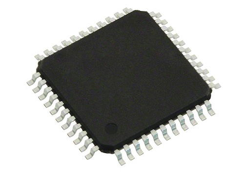
In the normal setup, the CPLD chip on the board is connected via a 3 foot cable to a vintage Macintosh. The Mac has 5V outputs. The CPLD has a 3.3V supply, with 5V tolerant inputs. In normal usage everything is fine, but I suspect there are occasional transients that cause a problem. From the CPLD datasheet: “The 3.3V VCCINT power supply must be at least 1.5V before 5V signals are applied to the I/Os.” In other words, the 5V tolerance of the CPLD’s inputs disappears if the CPLD’s supply voltage is under 1.5V. Could this be happening? What problem would that cause?
The board is powered indirectly from the Mac’s 5V supply, delivered by that 3 foot cable. When it’s first powered on, a 3.3V regulator on the board begins to work, and eventually it will raise the CPLD’s supply voltage to 3.3V. But what happens if the Mac applies 5V I/O signals before the CPLD’s supply voltage has risen above the critical 1.5V threshold mentioned in the datasheet? This might happen at initial power on, if the 3.3V supply is slow to ramp up. It would be even more likely to happen if the board were “hot plugged” while the Mac was already turned on. Or a similar issue might occur long after power-up, if something caused the 3.3V supply to droop back down below 1.5V while 5V I/Os were applied. This might happen during power-down, or because an SD card was hot-swapped in the board, causing a large inrush current to briefly overwhelm the 3.3V supply. In any of these examples, 5V would be applied to the CPLD inputs during a time when they were not 5V tolerant.
What problems might this over-voltage cause? The most likely result is damage to the ESD protection diodes. Most modern chips have some kind of protection circuitry at each pin, to guard against static electricity or a brief voltage overshoot. The exact design of this protection circuitry normally isn’t specified, but the typical example looks like this:
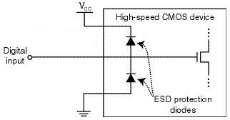
image from raspberrypi.org
In a typical chip, both protection diodes probably have a standard 0.6V drop. If the input goes below -0.6V, the bottom diode will begin to conduct, clamping the input voltage and preventing it from going any lower. If the input goes above VCC + 0.6V, then the top diode will begin to conduct, similarly preventing the input voltage from going any higher. When either diode conducts, a large amount of current may flow through the diode, depending on the resistance of the digital input line, and the output impedance of whatever’s driving it. I’ve failed to find any specifics on the CPLD’s diodes, but it seems they’re normally designed to tolerate very high voltages and currents, but only for a very brief time – like a few nanoseconds. Try to pass even a modest DC current through the diodes, like a few milliamps, and they may burn out.
In the case of this CPLD with its 5V tolerant inputs, I’m guessing the top diode actually has a drop of 2.2V instead of 0.6V (or it’s a few diodes in series with a 2.2V total drop). So under normal operation with a 3.3V supply for VCC, that diode wouldn’t begin to conduct until the input voltage exceeds the CPLD’s maximum rating of 5.5V. But despite the difference in voltage drop, the theory should be the same as with a standard ESD diode.
What’s going to happen if VCC is actually much lower than 3.3V, or zero? Then the diode will begin to conduct when the input voltage exceeds 2.2V, and it will keep conducting as long as this condition persists, or until it burns out. So how much current can the diodes tolerate, and for how long? I don’t know, and haven’t been able to find any straight answers, but I’ve seen estimates between 0.1 mA and 50 mA for max ESD diode current, with potential damage from transients that exceed that level for as short as a few milliseconds or even microseconds.
I don’t have any hard data to prove this theory, but it’s consistent with the observations I’ve made and with behavior reported by other people using the same CPLD in other applications. So until a better theory comes along, I’ll assume the problem is blown ESD protection diodes.
Possible Solutions
There are 12 I/O lines between the Mac and the CPLD. 10 of these are CPLD inputs: 5V signals from the Mac connected to the CPLD’s 5V tolerant inputs. One is a CPLD output: a 3.3V signal that’s still high enough to exceed the Mac’s 5V Vih threshold for a logical “1” value. The last can be an input or an output, depending on which kind of disk drive is being emulated. So I need a solution that ameliorates or prevents an over-voltage situation on 11 input pins, while also enabling one of those pins to be used as an output sometimes.
Inline Resistors – The simplest and cheapest solution is to add inline resistors in the signal paths of all 12 signals. Under normal operation, the inputs draw negligible current, so there will be negligible voltage drop across those resistors and the function of the circuit will be unaffected. But in an over-voltage situation where the CPLD’s VCC supply is too low and the ESD diode begins to conduct, the resistor will limit the current to a level that’s safe for the diode.
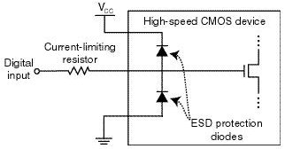
image from raspberrypi.org
The tricky bit is choosing what resistor value to use. There’s some parasitic capacitance on the cable, the board trace, and the CPLD input itself, and this capacitance combined with an inline resistor forms a classic RC circuit. The input voltage will no longer be able to change as rapidly before, rounding the corners of signal edges, and reducing the maximum signal switching rate that’s possible. So too high of a value for the resistor is bad. Fortunately the disk drive signals are comparatively slow, in the 1 or 2 MHz range at most. I estimate I could use a resistor as large as maybe 3.3K ohms before this RC filtering affect would cause problems, but I may be way off.
But wait! The resistor also needs to protect the ESD diode by limiting the current, and too low a value for the resistor will be ineffective. The minimum resistor size depends on the characteristics of the ESD diode, which are unknown. Let’s assume it has a 2.2V drop, and can tolerate 1 mA max. With a 5V input and the diode terminated to ground, that would leave 2.8V across the resistor, so a 2.8K ohm or larger resistor would be needed in order to limit the current to 1 mA.
Would this solution work? Probably, and it would only cost about $0.12 on top of the ~$1.20 assembly cost. But the overlap of resistor values is uncomfortably narrow between “too high for the circuit to work” and “too low to offer any protection”. And the values themselves are based partly on guesswork rather than any hard numbers from a datasheet. Some people feel that relying on the ESD diodes in any way is bad form, and the absence of real specs for the diodes is one reason why. Anyone with experience who might suggest an appropriate resistor value here that would satisfy both requirements – I’d love to hear from you.
Resistors with External Diodes – What about implementing my own over-voltage solution, external from the CPLD, with an inline resistor and a diode up to 3.3V for each signal? This would essentially do the same thing as the ESD diode, but with a beefier diode capable of handling more current, and for which I would know the actual specs. With a beefier diode, I could also get away with a smaller inline resistor, so the RC filtering effects would be reduced.
Standard silicon diodes with a 0.6V drop probably wouldn’t work. When the CPLD’s power supply is below the magic 1.5V threshold, its inputs aren’t 5V tolerant, but it’s not specified exactly what voltage is safe in this situation. If we assume 3.6V is the highest safe voltage, then the diode would need a voltage drop less than 0.3V.
The biggest problem with this approach is the number of parts required, and resulting cost. With a separate resistor and diode on all 12 signal lines, that would be 4 new pins/pads per signal line, or 48 new pins total. The assembly cost alone would be almost $2.00, without even considering the cost of diodes, pushing this solution to the point where it would cost more to implement than it would save. Maybe there’s some kind of single-chip ESD circuit solution I could use, that has a bunch of appropriate resistors and clamp diodes built into it? That might help bring the pin count down to a more manageable level.
Voltage Dividers – Another approach is to use a pair of resistors in series for each signal line to form a voltage divider. Something like this:
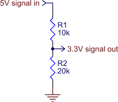
image from pololu.com
As long as the resistor values were in the proper ratio, and the 3.3V input itself drew minimal current, this would work OK as a level converter. It would prevent 5V signals from ever reaching the CPLD. The downside of a voltage divider is that when the 5V input is high, there’s current constantly flowing to ground. The IWM chip in the Mac is only able to source a paltry 0.32 mA for a high-level output, and to limit the current to that level, the combined resistance of the two resistors would have to be at least 15.6K ohms. That’s an awfully large resistance, and would probably create the types of unwanted RC filtering effects I feared would interfere with normal circuit operation. Using voltage dividers would also double the total number of components required for circuit protection, relative to inline resistors.
Level Shifter – The last solution I’m considering is a few level shifter chips. Any kind of chip would do, as long as it had non-inverting buffer outputs at 3.3V, with fully 5V-tolerant inputs. Candidates are the 74LVC244, or the 4050B. This would prevent any signal voltage above 3.3V from ever reaching the CPLD. With one input and one output pin per I/O signal, the number of pins and the assembly cost should be about the same as with passive resistors. A quick look at the 4050B shows I could buy a pair of them, enough to buffer 12 signals, for about $0.35 in quantity. That might work.
The problem with using level shifters is that they’re unidirectional. What about that one signal that’s either an input or an output, depending on the type of disk drive being emulated? This solution wouldn’t work for that, so I would need some additional bidirectional protection circuitry just for that one signal. I’m not sure what that might be or how complex it would become.
The other drawback of using level shifting chips is that they’re comparatively big, and it might be difficult to find space for them on the board without relocating everything and re-routing the whole thing from scratch. Resistors and diodes, even in multi-element packages, tend to be smaller and easier to squeeze into tight spaces.
Suggestions?
Have I analyzed the economics or the electronics wrong? Any other good solutions that I overlooked? Please leave your suggestions in the comments.
Read 19 comments and join the conversationApple IIgs ROM 03 Headaches
I’m still chasing an explanation for why some Apple IIgs computers won’t play nicely with Floppy Emu’s new 800K 3.5 inch Apple II disk emulation. I described the symptoms in my previous post – ProDOS and GS/OS disk images boot straight up on my IIgs without problems, and on most other IIgs systems, but for a couple of people it just hangs forever in the READ state on track 0. Both people who reported this have the relatively rare ROM 03 version of the IIgs, so I’m assuming it’s a compatibility problem between ROM 03 and the more common ROM 01. But what’s the problem exactly? And how can I fix it?
The biggest obstacle at the moment is lack of information. I don’t have a ROM 03 machine, and I can’t find one anywhere, so I can’t troubleshoot this myself. I’ve exchanged emails with two ROM 03 owners who are willing to help, but so far I’ve only gotten detailed information from one, and one data point isn’t enough to draw any conclusions. What seems like a compatibility problem might just be a hardware issue with one specific computer or Emu board.
Despite working mostly in the dark while trying to solve this, I have some theories about what might be going wrong.
Crazy WRPROT Circuits
There are documented incompatibilties between ROM 03 and some real Apple 5.25 inch floppy drives, although the details are fuzzy and sometimes seem contradictory. According to this section of the Apple 2 wiki, ROM 03 is not compatible with the Apple UniDisk 5.25 or DuoDisk. The explanation seems muddy, with two paragraphs that appear to offer two unrelated explanations, but one of them is related to the circuitry behind the drive’s WRPROT (write protect) signal. This is the signal that indicates whether the disk in the drive has the write-protect notch covered – remember those? According to the wiki, “incompatible drives on these models will just spin at startup.” Sounds a lot like what’s happening with Floppy Emu.
There’s also this Apple Tech Info document about ROM 03 and DuoDisk, with a symptom that sounds similar: “The DuoDisk LED for drive #1 will turn on, but the system will not start.” It doesn’t give an explanation, but mentions that booting from a write-protected disk works normally. Again, something about ROM 03 and write protection.
Check out this partial functional diagram of the Disk II 5.25 drive. Notice anything odd about the write protect signal?
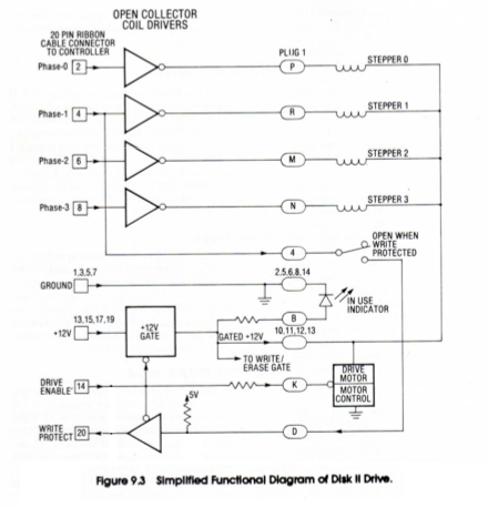
There’s a tri-state buffer for the WRPROT output, controlled by the drive’s ENABLE input. Behind that is a pull-up resistor, and the switch that senses the notch in the disk. But instead of ultimately terminating at GND, the write protect circuit is connected to the drive’s PHASE1 input. When the computer sets PHASE1 to 0, it can then read the WRPROT state as 1 = write protected, 0 = not write protected. But if the computer sets PHASE1 to 1, it effectively disables the whole write protect circuit, and WRPROT will always be 1.
My theory is that ROM 03 has some 5.25 inch drive detection code that sets PHASE1 to 1 in order to disable the circuit, and then waits for WRPROT to go to 1. But if the disk drive has its write protect circuit terminated directly to GND instead of PHASE1, it won’t be disabled, so WRPROT will never go to 1 and the computer will wait forever, unless the disk is actually write protected. My hunch is that the DuoDisk is built this way, which explains why it doesn’t work with the ROM 03 IIgs.
Floppy Emu’s Identity Crisis
Now what does any of this have to do with Floppy Emu’s 800K 3.5 inch Apple II disk emulation? After all, it’s emulating a 3.5 inch disk, where WRPROT behaves completely differently and this issue presumably isn’t relevant. Remember in my last post, when I described how the current design lacks connections for some enable signals used to distinguish between 3.5 inch and 5.25 inch drives? I had sort of dismissed it as not a problem, but my theory is it’s causing Floppy Emu to be identified as a 3.5 inch drive and a 5.25 inch drive. And when it’s identified as a 5.25 inch drive, WRPROT is not going to respond to PHASE1 in the expected way, which may cause a bootup hang on ROM 03 just like with the DuoDisk. My guess is that ROM 01 sees a misbehaving 5.25 drive and ignores it, but ROM 03 sees a misbehaving 5.25 drive and hangs forever, before ever attempting any 3.5 drive access.
The solution is simple, if annoying – use some external circuitry to handle all the enable signals, so Floppy Emu isn’t accidentally detected as a 5.25 inch drive. My last post sketched out a circuit to do this job, and I’m going to build some PCBs to test it. Meanwhile, using the daisy chain board removed from an AppleDisk 3.5 (A9M0106) floppy drive should accomplish the same thing.
SteveP, one of the ROM 03 owners I’ve been corresponding with, tested this theory. He used the A9M0106’s daisy chain board to connect Floppy Emu to his ROM 03 IIgs. And it worked! Sort of. The computer no longer hung at track 0 while attempting to boot. He was able to boot successfully into ProDOS. And he could begin to boot into GS/OS, but then it would fail with errors like “Unable to load START.GS.OS file. Error=$002E” or “UNABLE TO LOAD PRODOS”. So is there another ROM 03 compatibility issue at work here, or does he just have some flakey hardware or some other unrelated problem? With only this one report to go by, I can’t say, but I’ll keep digging.
Read 11 comments and join the conversation