

Archive for the 'Floppy Emu' Category
HD20 Firmware 0.2: Fewer Bugs, More Emus
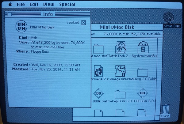
I’ve fixed most of the outstanding bugs in the HD20 emulation firmware. If you’ve been holding out for a way to attach huge SD card storage to your vintage Mac, this new firmware version is actually worth using. It’s still a read-only disk, and the data transfer rate can be improved further, but otherwise it’s totally usable as giant boot disk or a tool for transferring files between your vintage Mac and other machines. There doesn’t appear to be any limit on maximum disk size except the OS limit of 2 GB. If you already have a Floppy Emu board, you can use this with only a firmware update! And if you don’t have one, get one now!
- Fixed handling of the holdoff drive state. Now you can go crazy with the mouse during disk I/O without causing any problems.
- The disk’s Get Info window now says “Floppy Emu” for the disk location.
- Disk icon is a soothing round shape.
HD20 Firmware 0.2A-F65
See my previous post for notes about which Mac models are compatible, and how to apply the firmware update.
Read 5 comments and join the conversationHD20 Firmware 0.1
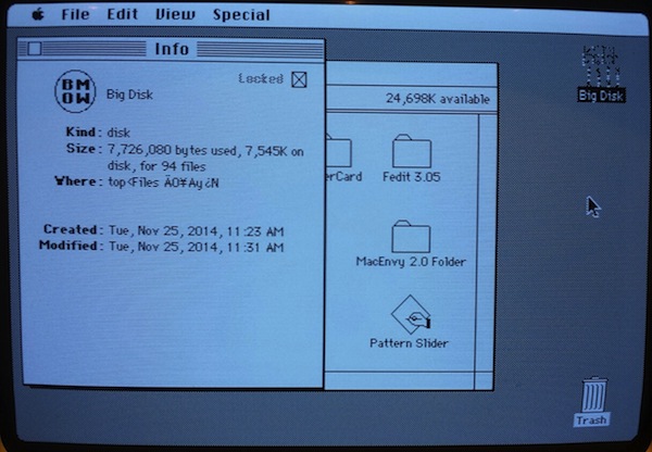
Good news, HD20-ers! I have rudimentary HD20 emulation working now, and I was able to use it to boot my Mac Plus. This runs on the standard Floppy Emu hardware, which means the same hardware can function as a floppy drive emulator or as a single large hard drive. If you’ve already forgotten, the HD20 was a mid-1980’s Macintosh hard drive that connected via the floppy port. Anyone with one of my Floppy Emu boards who’d like to help test this new firmware, grab the files and give it a try! But if you’re looking for something more complete and polished, you’ll need to wait a while more – this first firmware is very rough.
Version 0.1
- You can’t move the mouse during disk I/O, not even a tiny bit, otherwise bad things happen. It’s hard to avoid! The same thing goes for using the serial port, or anything else that will cause CPU interrupts. I had to single-click on icons and then press Cmd-O to open them, instead of double-clicking and accidentally nudging the mouse. Obviously this needs to be next on my list of things to fix.
- This is read-only emulation for the time being. The disk appears with a lock icon in the Finder.
- The disk icon on the desktop looks like random garbage. But in the disk’s Get Info window, it looks fine. Something about needing an icon mask, maybe? But there’s no place in the HD20 drive status structure to supply an icon mask, as far as I can see.
- In the disk’s Get Info window on System 6.8, the “where” field shows random garbage. For a SCSI disk, this field shows “SCSI1”. If someone has a real HD20, please do Get Info on the disk and let me know what it says for “where”.
- SD card transfers are totally unoptimized, one block at a time reads. This should be possible to improve significantly. But it still feels decently fast already: at least as fast as a floppy if not more so. It boots up to the desktop in 5-10 seconds.
I need help testing which Macintosh models have built-in HD20 support, and which don’t but can use an HD20 after booting from another disk with the appropriate software. From what I’ve learned so far, I believe these Macintosh models have HD20 support built into ROM:
- 512Ke
- Plus
- SE
- Classic
- Classic II
- Portable
- IIci
- IIsi
- LC (but not LC-II or LC-III)
The Mac 512K and 128K can use an HD20 if they boot from another disk that contains Apple’s HD20 Init. That Init may also work for other II-series machines that lack HD20 support in ROM. HD20 Init shipped with very old version of the Macintosh system software, and I’m still looking for a download link for it. Let me know if you’ve got one.
You’ll need to connect the Floppy Emu board to the external floppy port, not the internal one. For the LC, one of the two internal floppy ports is considered “external” – try them both to find which works.
I would also appreciate help testing different sizes of disk images. The HD20 was a 20 MB drive, but its communication protocol can support larger drives. The limit is either 32 MB or 8 GB, but I’m not sure which. Just because the computer boots and says there’s a 1 GB disk doesn’t mean it’s actually working though. It’s necessary to test reading files from all parts of the disk to make sure the full capacity is actually working correctly. The OS itself also imposes a limit of 2 GB for disks.
Let’s Do This!
When you program this firmware to your Floppy Emu hardware, it will no longer function as a floppy drive emulator until you program it again with the old firmware. Before you begin, take note of what firmware version you’re currently using. This is displayed on the LCD for a few seconds after a reset – look for a string like “App Version 1.0 Q, CPLD Firmware 13”.
Program the hardware with firmware HD20 0.1A-F64. Edit: see this later post for newer firmware that fixes most of these issues. Instructions for applying the firmware update are included with the download. Note that the update comes in two parts: a new application for the microcontroller, and a new configuration file for the CPLD. You must apply both parts.
To use the emulator, put a file named “HD20.dsk” on your SD card, put the card in the Floppy Emu, and reboot. The disk image file format is the same as the disk images from popular emulators like Mini vMac and Basilisk II, so have fun. If your image file ends with a .dsk or .hfv extension, you can probably just rename it to HD20.dsk with no other changes necessary. If you don’t have an appropriate disk image handy, try this one.
When you’re done playing, reprogram the old firmware. If you were previously using 1.0L-F11 or earlier, restore the hardware to 1.0L-F11. If you were previously using something later than 1.0L-F11, restore the hardware to 1.0Q-F13. If you get messages about “bad fuses” or “wrong CPLD” after restoring the old firmware, don’t panic – it means you’ve programmed the wrong firmware, or only programmed one of its two parts. If you get really stuck, email me.
Read 7 comments and join the conversationReverse Engineering the HD20
Finally after nine months, a progress update on HD20 emulation! Back in February I wrote about my efforts to reverse engineer the Apple HD20, an external 20 MB hard drive for the Macintosh that was introduced way back in 1985. This was before the introduction of SCSI support, so the HD20 connected via the Mac’s floppy port. With luck, that might make it possible to emulate an HD20 using the hardware I previously developed for Floppy Emu, the Macintosh floppy drive emulator. 20 MB (or more?) of external storage for a Mac Plus or other vintage machine, stored on an SD memory card, with no dependencies on SCSI or aging rotational disks! But doing it would require understanding how the HD20 worked well enough to emulate it.
A Little History
The HD20 has a famously strange reputation. Despite sharing the same DB-19 connector as a floppy drive, it used an entirely different communication protocol. When SCSI support was introduced in 1986, external hard drive solutions quickly adopted the new standard, so the HD20 was the only hard drive to ever use this protocol. The protocol was never documented anywhere publicly, and eventually became an old, obscure mystery. Emulating the HD20 was virtually impossible.
Then about a year ago, a couple of ancient Apple internal documents about “directly connected disks” surfaced on the internet. The term “HD20” didn’t appear anywhere in them, but it was clear that’s what they were about. Two docs dated March 1985 and May 1985 outlined the DCD communication protocol. They described a state-based command-and-response system, in which data was transferred in groups of 7 logical bytes encoded into 8 physical bytes. But the docs conflicted with each other in many details, and were silent on other critical points. And as I later discovered, both docs conflicted with tests performed on a real Macintosh system. Still, it was enough to get started. In my February experiments, I got as far as fooling the Mac into believing an HD20 was connected, and receiving/decoding a drive status query. But I was never able to send back a reply, and I eventually lost interest.
New Preparations
Thanks to a slow trickle of people who kept encouraging me to look at it, I recently dusted off the HD20 project again. I could receiving a drive status query, but how could I send a reply? What kind of handshaking was needed to tell the Mac a reply was ready? How big was the reply, and what data did it contain? What checksum method did it use? Armed with the DCD docs and some educated guesses, I programmed the Emu hardware to send a drive status response. Then to test it, I wrote a Macintosh program to read arbitrary sectors from disk ID #2, the first connected DCD.
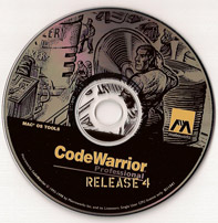
Side note: it’s not a simple thing to write new software for a 30-year-old computer system! In order to create my test program, I used an old copy of Metrowerks Codewarrior, running under emulation in Basilisk II. The finished program was saved to Basilisk’s virtual hard disk image. Then I mounted a virtual floppy disk image in Basilisk, and copied the program to it. After quitting Basilisk, I copied the floppy disk image file to an SD card, put the SD card in a second Floppy Emu (the first one having been turned into an HD20 Emu), booted my Mac Plus with the Floppy Emu attached, mounted the floppy image, and copied the program file to the Plus’s external SCSI disk. Oof!
The Mac really doesn’t like to boot if it thinks there’s a sort-of-working HD20 attached. It either hangs for long periods, or complains endlessly about disk errors. If I used the SCSI drive and managed to boot into the Finder, the Finder would freeze forever while trying to communicate with the emulated HD20, so I could never actually launch my test program. Doh! My solution was to configure the Mac to run the test program immediately at boot-up, instead of running the Finder. With the not-really-an-HD20 disconnected, this can be done by highlighting the test program, then selecting the Finder’s Special -> Set Startup menu.
Crawling towards Two-Way Communication
At last I had something to test, and of course it didn’t work. The test program reported error -17, which according to Inside Macintosh means “driver can’t respond to this control call.” I could tell my hardware was receiving the drive status command, and trying to send a reply, but beyond that I was blind. Did the Mac receive the reply, but reject it as misformatted? Was it the wrong size, or encoded incorrectly? Maybe the handshaking wasn’t working, and the Mac wasn’t even seeing any response at all? No matter what I did or what I tried, all I got was error -17, with no further clues to help me troubleshoot.
From another Apple document, I knew there were supposed to be HD20-specific error codes, and I could see places in the Mac ROM disassembly where those errors were generated. They are:
; New HD20 error codes

wrtHsLw         equ     $10             ; HSHK low before starting
wrtHSLwTO       equ     $11             ; Time out waiting for HSHK to go low
wrtHSHighTO     equ     $13             ; Time out waiting for HSHK to go high
rdHsHi          equ     $20             ; HSHK high before starting
rdSyncTO        equ     $21             ; Time out waiting for sync ($AA) bye
rdGroupTO       equ     $22             ; Time out waiting for group
rdHoffSyncTO    equ     $24             ; Time out waiting for sync after holdoff
rdHsHiTO        equ     $25             ; Time out waiting for HSHK high
rdChksumErr     equ     $26             ; Checksum error on response packet
invalidResp     equ     $30             ; First byte in response packet was wrong
sqncNumErr      equ     $31             ; Sequence number in response packet was wrong
dNumberErr      equ     $32             ; Drive number in response packet was wrong
noResp          equ     $40             ; No response packet ever received
Those are some great low-level error codes covering handshaking, checksums, and other details. Why was I only getting error -17, instead of the more detailed codes? With no useful feedback, I continued pounding away at the problem blindly for far longer than I should have, but got nowhere.
Something was generating that -17, and I was determined to find out what. On the early Macs, most of the operating system code is stored in ROM, and this includes the HD20 I/O routines. It’s possible to pull those ROMs, dump the data from them, and run it through a 68000 disassembler. Other people have done this long ago. But the result is only useful to a point – it’s just raw assembly language code, without any symbolic names or comments or any other context to help understand what it’s doing. Just thousands of lines like these:
SubA.L    A4, A4
SubA.L    A5, A5
MoveQ.L   $1, D3
MoveQ.L   $0, D6
MoveQ.L   $0, D7
Move      $64, $1C0(A1)
Move      $4650, $1C2(A1)
Cmp.B     $3, $19C(A1)
BNE       L4809
Move.L    $14C, D7
Move      $A, $1C0(A1)
Move      $2710, $1C2(A1)
Lea.L     $1C4(A1), A4
Ugh. But with slow and painful effort, it’s eventually possible to make at least partial sense of it all. For example, looking backwards from this code, I can see that A1 was previously loaded from memory location $000134, which I know from other Mac programming resources is a pointer to a structure containing drive state, called SonyVars. So all those references like $19C(A1) in the code above are offsets into this SonyVars structure. And from yet another Apple internal document, I learned that offset $19C in SonyVars is the DCD command number. So here’s some code that (in part) checks if the command number is 3 – the drive status command, and branches away somewhere else if it’s not. If it is command 3, it stores the curious number $14C (332 decimal) in another register. Which after more tedious analysis, turns out to be the size of the expected drive status reply. Except for some extra padding and modulo-7 business, which I discovered after still more analysis.
If you feel dizzy, I’ll pause for a moment if you want to lean over and vomit.
Here are the DCD-specifc SonyVars offsets and constants that I learned:
sonyVarEnd      equ     $128
; (4) Direct-connect driver locals.

TagSize         equ     20                      ; 20 bytes tags/block
dcdLclLth       equ     28                      ; (use fields through DriveMisc)
drive3          equ     sonyVarEnd              ; first DCD
drive4          equ     drive3+dcdLclLth        ; second DCD
drive5          equ     drive4+dcdLclLth        ; third DCD
drive6          equ     drive5+dcdLclLth        ; fourth DCD
stsRtnAddr      equ     drive6+dcdLclLth        ; DCD status call return address
dcdCmd          equ     stsRtnAddr+4            ; command byte to DCD
response        equ     dcdCmd                  ; response byte (command+$80)
seqNum          equ     response+1              ; mb sequence number (sys commands only)
status          equ     seqNum+1                ; returned status bytes
startBlock      equ     status                  ; starting block # (in commands)
driveOut        equ     startBlock+3            ; we send drive number in this field
driveIn         equ     status+2                ; low 6 bits
tagBytes        equ     status+4                ; tag bytes get stuffed here temporarily
devType         equ     tagBytes                ; first 20 bytes of status are written
devManufctr     equ     devType+2               ;       in the 20-byte tag buffer
devChar         equ     devManufctr+2
devBlks         equ     devChar                 ; low 3 bytes of this longword
devSpares       equ     devChar+4
devBadBlks      equ     devSpares+2
devMisc         equ     devBadBlks+2            ; 8 bytes misc
bufSize         equ     tagBytes+tagSize        ; number of bytes/block
lastStatus      equ     bufSize+4               ; last status returned
lastResult      equ     lastStatus+4            ; error type
dcdFlags        equ     lastResult+1            ; flag of whether we've done a reset
chkTime         equ     dcdFlags+1              ; 100usec check ready count
maxTime         equ     chkTime+2               ; maximum number of checks
stsBuffer       equ     maxTime+2               ; 512 bytes of status
devReserve      equ     stsBuffer
devIcon         equ     devReserve+44
devFiller       equ     devIcon+256             ; 32 bytes for optional name
diskVarLth      equ     devFiller+32
stsBufSize      equ     diskVarLth-stsBuffer

; device characteristics byte:
devChEject      equ     4               ; ejectable if 1
devChWP         equ     3               ; write protected if 1
devChIcon       equ     2               ; icon available if 1

; (4) Direct-connect drive constants.
blkSize         equ     512             ; 512 bytes data/block
syncByte        equ     $AA             ; Sync byte for start of transmission

noError         equ     0               ; resultTypes
nonZerStat      equ     1
comErr          equ     2
Applying these offsets and constants to the ROM disassembly, and doing many hours of analysis, I was finally able to construct a halfway decently commented version of the HD20 I/O routines. It’s not pretty, but it’s enough to resolve the conflicts and unanswered questions left by the DCD documents. Take a look, if you dare: macintosh-HD20-io-routines.asm
Checksum Error
This ROM analysis finally revealed one crucial fact: the “missing” HD20 error codes were packed into the most significant byte of the 4-byte value lastStatus, which is set by the disk I/O call. My test program had been displaying this value all along, in decimal format. I had seen lastStatus values like 637534208, but just assumed it was some uninitialized garbage value. But wait, 637534208 in hex is $26000000, and from the table above, $26 is the error code for “checksum error on response packet”. HOLY SHIT! This was my eureka moment, my Rosetta Stone, when I was finally able to get meaningful feedback instead of those blasted error -17’s. I could make changes in the emulator routines, and see changes in the error codes reported by the Mac, and start to do real troubleshooting. Yes!
A checksum error could be caused by many things. I might have the wrong checksum algorithm, or be putting the checksum value in the wrong spot, or encoding the whole message improperly, or any number of other mistakes. Without being able to see the data as it was received by the Macintosh, it was hard to say what was wrong. I was about to get out my oscilloscope and logic analyzer, but then I took another look at the ROM disassembly. After a drive status response, even if there was a checksum error, the response data should be available at SonyVars+$19C. I already had MacsBug installed on my Plus, so I hit the interrupt switch, and used the dm command to display the region of memory. Ta-dah! There was my response data, seemingly received perfectly:
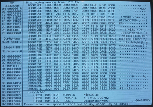
The first byte was $83, which was the command number plus $80. Afterwards followed a pile of other fields and flags, some of which I filled with sequences of consecutive numbers so I could recognize them in the debugger. But there were a few oddities, like the 14-byte break between 07 and 08 in the sequence on the second and third lines. At first I thought this was a bug in my sending code, but it turns out that the Mac actually stores it this way intentionally. I don’t know why, but from examining the ROM disassembly, it’s clear that after the first 26 bytes are received, it jumps the buffer pointer to a new address and stores the remainder of the data there.
The other odd thing about this memory dump completely escaped my notice at first. In the sequence ending on the 22nd line, notice how the last two bytes are FCFC? The expected continuation of consecutive values should be FCFD. This was a clue whose meaning I didn’t discover until later.
Unfortunately, the ROM routines don’t actually store the checksum byte itself, so I couldn’t use MacsBug to examine it and see why it was wrong. It was that FCFC value that finally led me to the answer. For reasons I still don’t understand, it appears that the last byte in a transmission I send from the Emu hardware to the Mac isn’t received correctly. The last byte contains the least significant bits of the preceding seven, which include the checksum byte. By appending an extra dummy byte onto the end of the transmission, the LSB byte was now received correctly, and the last seven bytes before it could be correctly reconstructed.
Once I made this fix, the test program started reporting something new: error -19, read error. And the Emu received a new command after #3 drive status: command #0, read block. The Mac had accepted my drive status reply, and was continuing on to perform a read request! Two way communication at last! Of course I hadn’t implemented a handler for block read requests yet, that was next. But it was time to take a break, and celebrate my progress to this point.
Here is the correctly-formatted drive status structure:
#define DEVICE_CHAR_DISK_IN_PLACE 0x02
#define DEVICE_CHAR_ICON_INCLUDED 0x04
#define DEVICE_CHAR_WRITE_PROTECTED 0x08
#define DEVICE_CHAR_EJECTABLE 0x10
#define DEVICE_CHAR_WRITABLE 0x20
#define DEVICE_CHAR_READABLE 0x40
#define DEVICE_CHAR_MOUNTABLE 0x80

struct DriveStatus
{
	uint16_t deviceType;
	uint16_t deviceManufacturer; // Apple = 1
	uint8_t  deviceChars; // characteristics
	uint8_t  numBlocks[3]; // 3 bytes number of blocks on device
	uint16_t numSpares;
	uint16_t badBlocks;
	uint8_t  reserved[52];
	uint8_t  icon[256];
	uint8_t  padding[16];
};
The structure is 336 bytes. A valid drive status response is:
$83 - command number plus $80
$00 - pad
$00 - status high byte, zero means no error
$00 - status low byte, zero means no error
$00 - pad
$00 - pad
DriveStatus struct
checksum - choose this so the sum of all bytes (including this one) is 0 modulo 256
This is 343 bytes. Then the response must be encoded using the 7-to-8 encoding method described in the DCD doc, and in my posting from last February. This results in 49 groups of 8 encoded bytes each that are actually sent to the Mac.
Checksum Non-Sequitur
Story time about checksum errors: my first computer was an Atari 800, which my family bought when I was 12. Day 1 when it arrived from the store, I attempted to load my very first program from cassette tape. The Atari reported “ERROR 143”. Confused, I consulted the printed manual to learn that error 143 meant “SERIAL BUS DATA FRAME CHECKSUM ERROR”. This was the full explanation, and the only help provided for the error. At the time, those words made as little sense to me as “BYTE VECTOR DIRECTION BUFFER INTERRUPT” might have, and I nearly threw the machine out the window. Fortunately it worked the second time I tried it, and my future in computer technology was assured.
Whee!
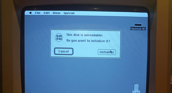
To prove that the drive status response was really working, I whipped up an ugly BMOW icon, and stuffed its bytes into the icon field of the DriveStatus struct sent from the Emu. Now when I try to mount the emulated HD20 in the Finder, I see the message shown in the photo at the top of this post. Woohoo, that is one ugly icon! But it comes from a successfully received drive status reply, so that makes it awesome.
There are still plenty of other issues to resolve before I can get full HD20 emulation working, not the least of which is actually implementing the read and write commands. Beyond that, here’s a strange one – if you move the mouse during a data transmission, it fails! The Mac ROM routines poll the SCC and VIA chips during HD20 transfers, and if there’s a pending interrupt, it puts the HD20 into a holdoff state so it can service the interrupt. I’m a little hazy on the details of how that works, and I haven’t yet tried to implement the holdoff logic. So for now if you move the mouse or do anything else to generate an interrupt, the transfer fails.
The bigger issues may be unrelated to the HD20 code itself. My current prototype uses the Floppy Emu hardware, but it replaces the Floppy Emu software rather than adding to it. In particular, I don’t think there are enough logic resources in the Emu’s CPLD chip to handle both floppy and HD20 emulation. This would mean you’d have to flash new firmware every time you wanted to switch between emulation types – not exactly a great user experience.
It’s also unclear which Macintosh models could make use of HD20 emulation. The Mac 512Ke and Mac Plus definitely have HD20 support in their ROMs. The Mac 512K can use an HD20 if you first boot it with a System file containing the HD20 Init – but that would require having a working floppy drive and floppy disk, or a second Floppy Emu to serve as the boot disk. According to mac512k.com, the Mac SE, Classic, IIci, and Portable also have HD20 support in ROM, but the SE/30, II, IIx, IIcx, IIsi, IIfx, and LC don’t. I assume that means anything newer than those machines doesn’t have HD20 support in ROM either. It’s not clear if newer machines could make use of the HD20 System Init, but if they could, they’d be subject to the same requirement of having a working floppy drive & disk or a second Floppy Emu for booting.
Even if HD20 emulation only proves useful to owners of the 512Ke, Plus, SE, Classic, Portable, and IIci, that’s still a lot of people! If any Floppy Emu owners with an SE/30, LC, or II-series machine other than the IIci would be willing to help test this, please let me know.
Read 6 comments and join the conversationFloppy Emu, Year 1
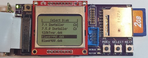
It’s been roughly a year since I turned a personal electronics project into a retrocomputing mini-business, which makes now a good time for a short review. When I started dabbling in floppy disk emulators for vintage Macintosh computers, I never would have guessed there would be other people out there who wanted one of their own. It’s been an interesting adventure!
After selling a few prototypes on eBay, and giving away a few boards as gifts, the first real sale was board S/N #0008 on December 9, 2013. Since then I’ve made 223 Floppy Emu boards, sold 182, junked 4 that had defects revealed in testing, replaced 2 that had problems during the warranty period, and have 35 in inventory (aka my floor).
The first 123 boards were built by hand, one at a time, one component at a time. There’s not a lot to say about that experience except that it sucked, and I inhaled a lot of leaded solder fumes. Of those 123, there were 3 with major defects that had to be junked, and 4 more that only worked at 400K/800K disk speeds and were sold at a discount. Since serial number #0121, all boards are now professionally assembled by Microsystems Development Technologies in San Jose, CA. That’s helped improve the quality, and restore my sanity. Of the 55 boards from Microsystems that I’ve tested thus far, only one has had a defect.
Initially, all Floppy Emus were sold with a built-in DB-19 floppy connector, so the board could be plugged directly into a Mac’s rear floppy port. I later introduced a version with the DB-19 on a 3 foot extension cable instead of soldered directly to the board, and that’s proven to be very popular. Since mid-August when I lowered the price of the extension connector model by a few bucks, it has outsold the built-in connector model by 4:1. At some point I’ll probably drop the model with the built-in connector, and standardize on the extension connector model for all sales.
Cases for Floppy Emu have only been available for a short while, but they’ve been well-received. The attachment rate for cases (percent of people buying a board who also buy a case) has been 83%, much higher than I’d expected. And despite my predictions, the brown hardboard case has been much more popular than the clear acrylic case. I’ve already sold out of the hardboard cases, and just placed an order today to manufacture more.
About 50 percent of sales have been to the United States, which isn’t too surprising since that’s where I am. Australia, Canada, and the UK have also all seen significant sales. No sales to Africa or Antarctica yet, but all the other continents are represented.
Shipping has gone smoothly, even internationally. I’ve only had one shipment (to New Zealand) that never reached the buyer.
My order handling and fulfillment process is still horribly inefficient, but there aren’t enough sales to justify a big investment in streamlining things. Between manually testing each board on a Mac 512K and a Mac IIsi, downloading Paypal order details, fighting the post office web site to print electronic postage, generating sales receipts, wrapping boards, packing boxes, and driving to the post office, there’s about 30 minutes of labor time required for every single sale. Then there are often post-sale questions, which require additional support time. It’s not exactly a low-overhead business.
I’m excited to see what year 2 will hold for Floppy Emu. Thanks for coming along for the ride!
Read 2 comments and join the conversationFloppy Emu Cases are Here!
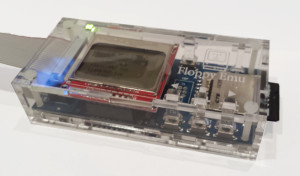
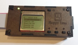
Custom-made cases for Floppy Emu are finally here, and available for sale now on the Floppy Emu home page! These laser-cut enclosures will keep your board protected in style. The clear acrylic universal case is $17, and fits all models of Floppy Emu boards. The deluxe brown hardboard case fits the Floppy Emu with Floppy Extension Connector, and is $19. Both styles of case require assembly, which takes about 10 minutes and a screwdriver.
The prototype cases are also available for sale at a small discount, including black acrylic and birch plywood. The dimensions on the prototypes are slightly different, so they’re a bit more fiddly to assemble, but once assembled they look and feel the same as the regular cases.
I’m also testing out a new shopping cart interface for the first time, so let me know if you have any trouble while making a purchase.
Acrylic, Wood, Hardboard, Oh My!
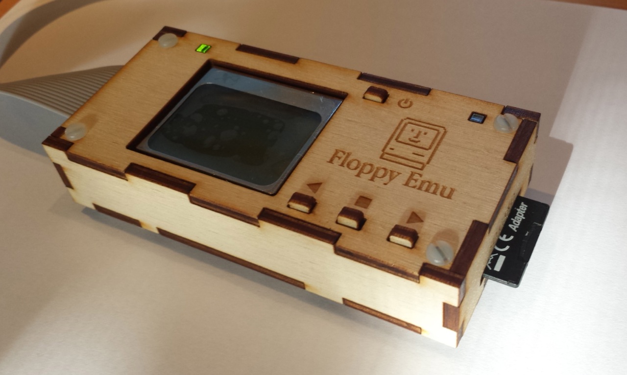
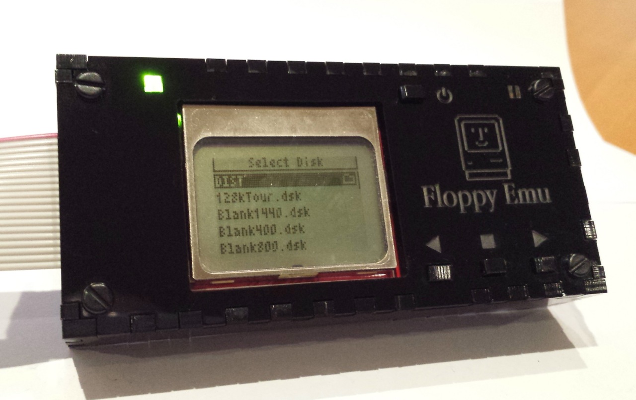
The revision 4 Floppy Emu cases are here, and they look great! Clear and black acrylic in different layouts, birch plywood, and chocolate-colored hardboard. I’m having too much fun putting these together. The purpose of revision 4 was to test a few layout tweaks and a sampling of different materials, so I could decide which one to get manufactured in larger quantities. The layout changes are probably the most important, but first let’s talk about materials.
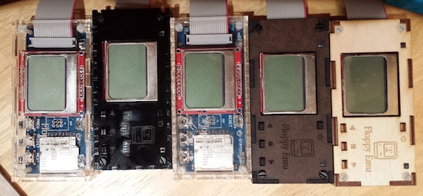
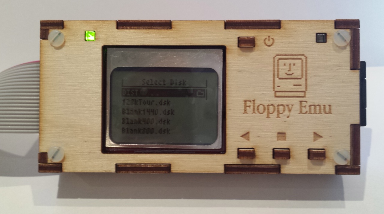
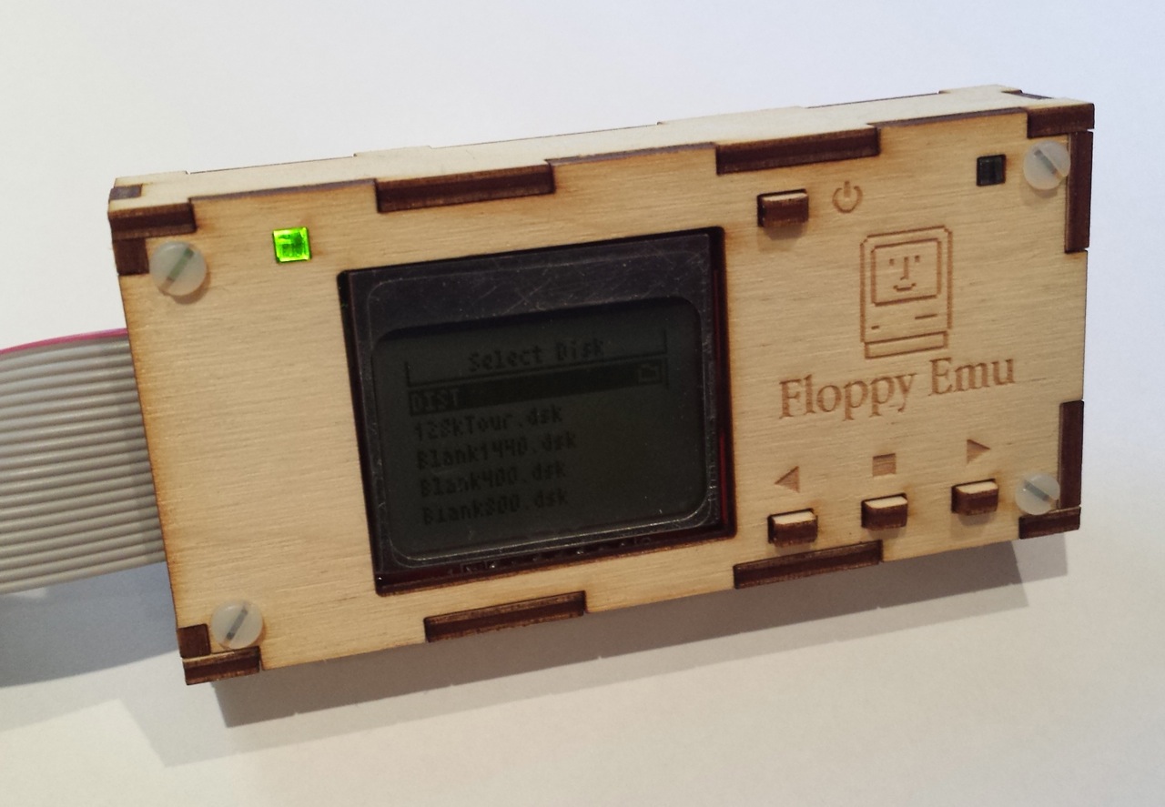
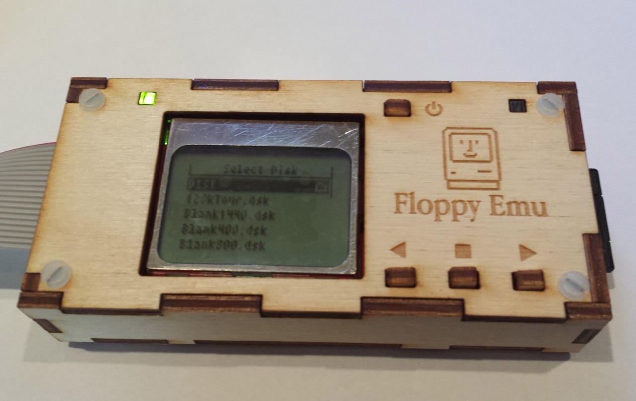
First is a birch plywood. It’s actually just a thin birch veneer over some kind of filler layer, but it still looks very nice. You can see the veneer layers when you look at the board edge-on, and the edges are quite dark in color compared to the face of the board. This gives the case a high-contrast look. The engraved logo and text came out well, although they probably could have been a bit darker. The areas of the the board near the holes and corners are baked a darker shade of brown from the heat of the laser. The white case screws look decent with the light birch, though it’s not the best match. Overall the plywood case came out well, but I can’t say it’s my favorite.
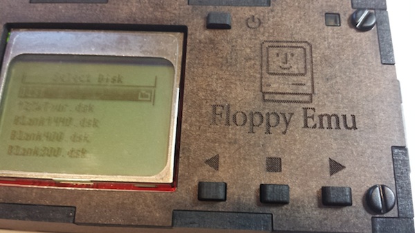
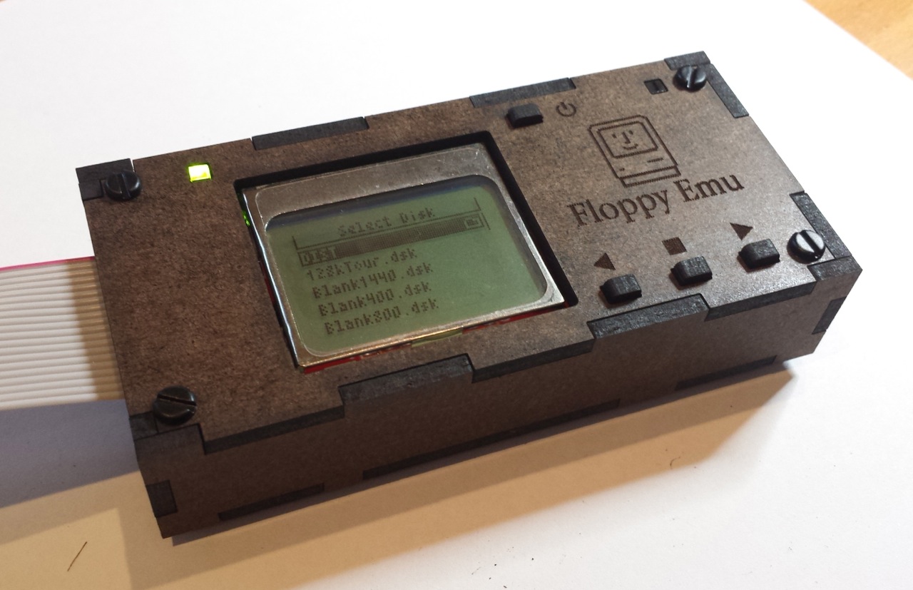
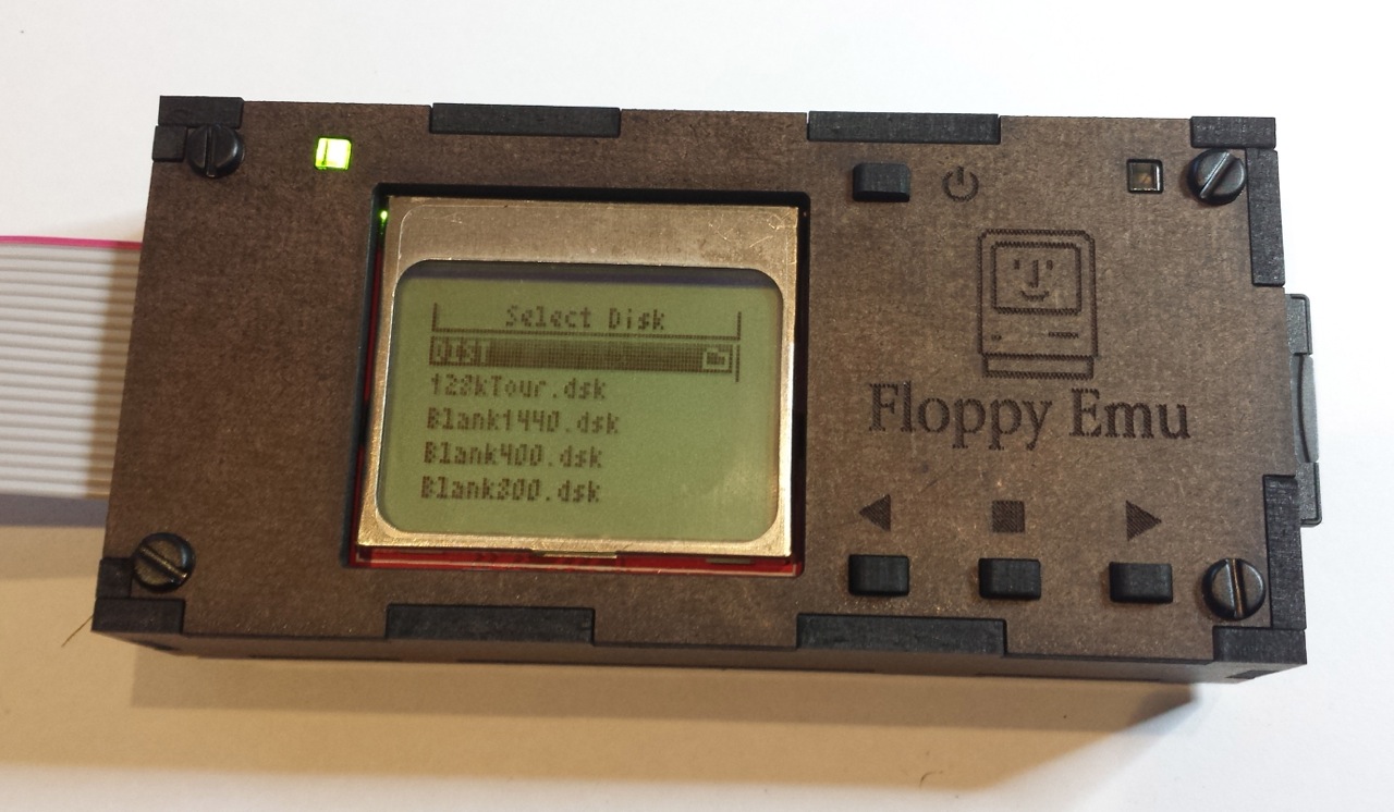
Second up is hardboard, which is just a higher-density version of the ubiquitous MDF fiberboard. You might think fiberboard is icky, but this case came out great and is easily my favorite. The faces are a dark chocolate brown color, while the edges are near black, and the combination looks nice together. The black case screws accent it nicely too. The engraved logo and text are clearly visible, yet still understated. The quality of the engraving is also extremely sharp and crisp. There’s no darkening of the board near holes and corners, like occurred with the plywood. The one big drawback of hardboard is that it requires more than twice as much laser time to cut than the other materials do, which increases its cost. If I sold a hardboard case, it would have to be for $4 or so more than a case made from acrylic or plywood.
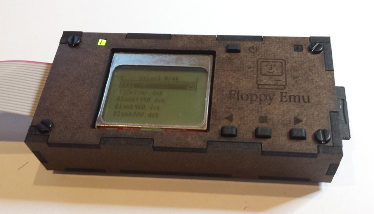
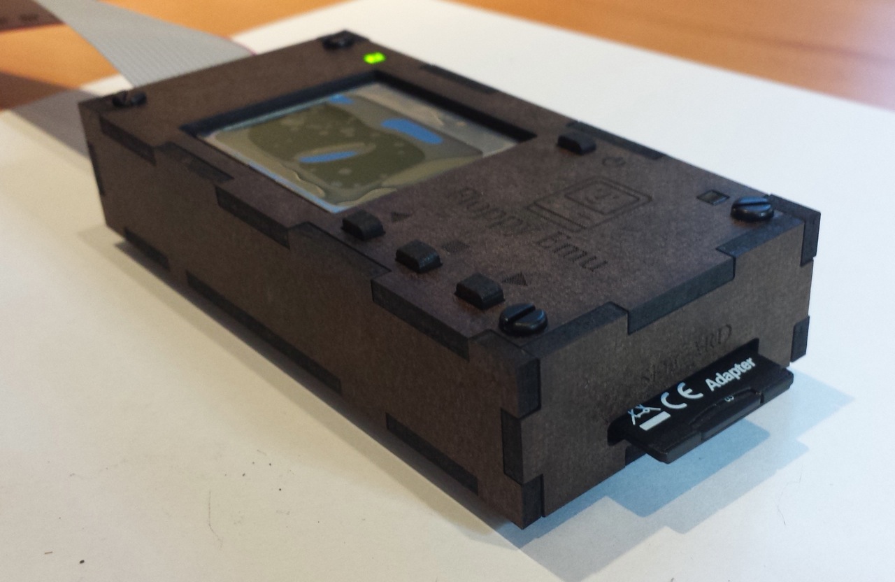
Black acrylic came out well too, and as expected it’s very similar to the previous cases I did in clear acrylic. I’m not in love with it, though. It’s very glossy, and it shows every fingerprint and smudge. The engraving is pretty good, but it’s like matte gray set against shiny black, and is difficult to see from some angles. Maybe it’s good… I can’t decide.
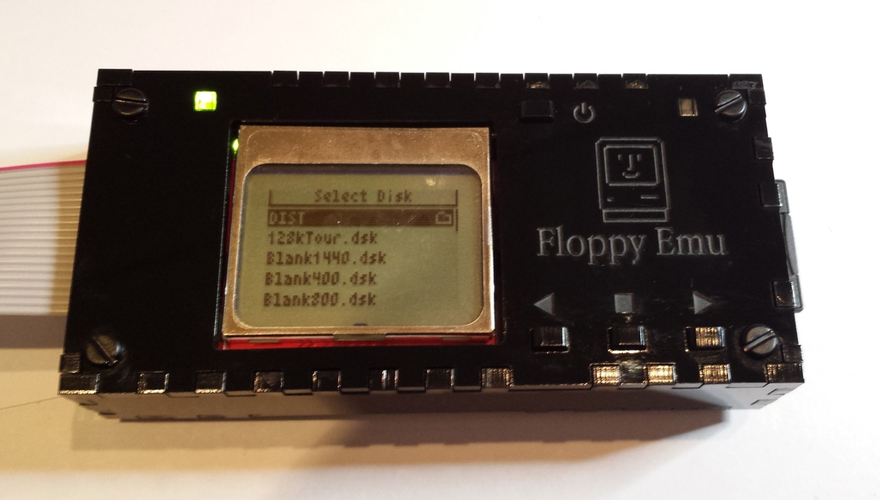
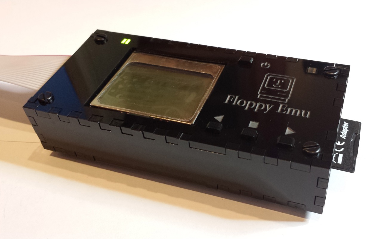

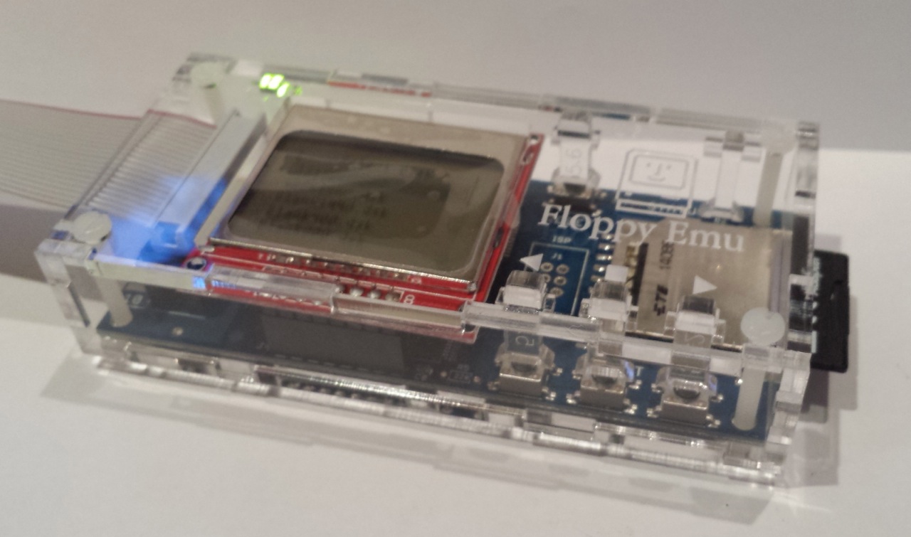
The new clear acrylic case is almost identical to the old one, except I’ve increased the sizes of the finger joints from 4 mm (as shown on the black case above) to 18 mm. This gives the edges a much less busy look, and helps the pieces fit together more easily. Clear acrylic shows fingerprints too, though not as much as black. And everybody likes clear, right?
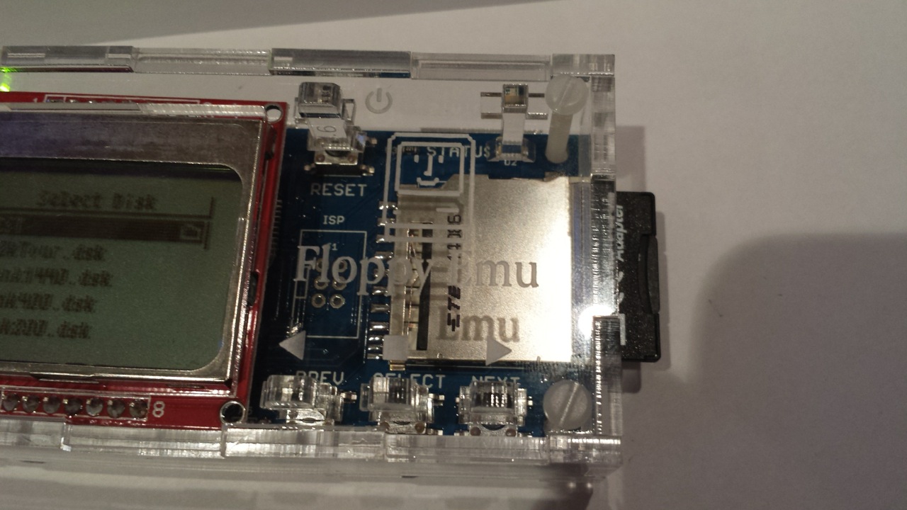
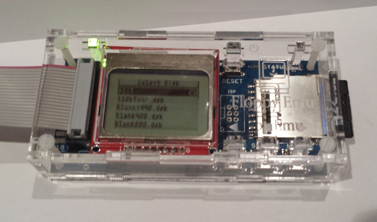
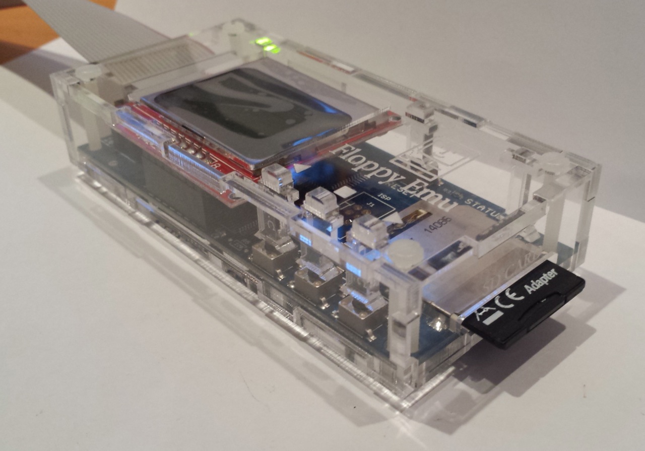
I don’t have photos of the layout changes, but they’ll help save manufacturing dollars and assembly headaches. Believe it or not, going from 4 mm to 18 mm finger joints cuts almost $1 off the cost of the case. Fewer direction changes for the laser as it’s cutting means it can finish the job quicker. I also eliminated the two extra pieces I’d been using to accommodate boards with a built-in floppy connector, and instead there’s now a punch-out section on two of the boards that can be removed if necessary, opening a space for the connector. I tested the punch-outs in acrylic and they worked well – didn’t break loose accidentally, but could be broken off using only finger pressure when needed. I didn’t think to include punch-outs in the two wooden cases, but hopefully they’ll work equally well there.
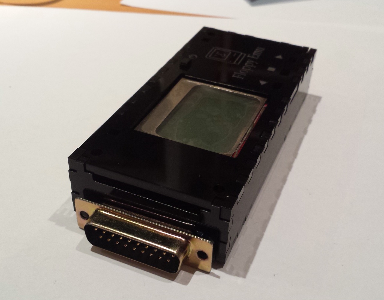
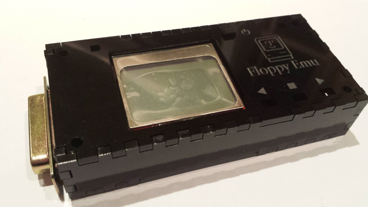
I also made several tiny size adjustments to help make the “swords” for the LEDs and buttons fit just right. And I didn’t quite get it perfect, but now I think I have the dimensions I need to nail it next time. The buttons have tiny nubs on them to help prevent them from slipping back through the top plate while you’re assembling the case. This worked pretty well, but wasn’t 100% reliable. I suspect it will still be necessary to use the tape trick during assembly that I described last time. Hopefully people won’t mind that too much.
Armed with all this information, I think I’m about ready to do a larger manufacturing run of at least a few dozen cases. Given what I saw from these, I’ll probably make the majority of them clear acrylic, and maybe make a few hardboard ones I’ll sell for a couple dollars more as “premium cases” or similar. Thanks to everyone who wrote in with their preferences and requests. Check back in about 10 days and I hope to have a stock of new cases ready to go!
Read 2 comments and join the conversation