

Archive for the 'Floppy Emu' Category
In-System CPLD Programming Using XSVF Files
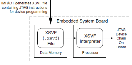
Floppy Emu has both a microcontroller and a CPLD working in tandem, and both must be programmed in order for the emulator to function. However, I don’t want to require two separate external programmers and the associated port connectors. My plan is to use a standard external ISP programmer for the microcontroller, but have the microcontroller program the CPLD, using the technique described in Xilinx app note XAPP058. The idea is to have the microcontroller act as an XSVF player, loading the CPLD configuration file from the SD memory card, and bit-banging the four JTAG pins on the CPLD to perform the programming.
This week, I finally got around to working on the XSVF player so I could program the CPLD on the Floppy Emu prototype board. The Xilinx player sample code is written in C, and was fairly easy to integrate into the emulator program. Using the functions I’d previously implemented, it was quick work to add an option to load a config file from the card and execute it with the XSVF player.
Predictably, once all the pieces were in place, it didn’t work. I spent a while checking and re-checking all my assumptions, reviewing the code, and writing debug info to the LCD, but made no progress. Finally I used the oscilloscope to peek at the JTAG signals, and discovered that they weren’t wiggling at all. All four JTAG signals were stuck high. I spent a few more hours chasing various theories why that might happen, and double-checked the electrical connectivity, before I gave up to do something else. Immediately after leaving the room, I suddenly realized what the problem was: in order to programmatically control the microcontroller JTAG pins, the JTAGEN fuse must be turned off, to disable hardware JTAG. Once I did that, the signals began wiggling as expected when I ran the XSVF player.
At this point the outgoing TMS, TCK, and TDI signals looked reasonable, but the JTAG communication still didn’t work. The error code from the player indicated that the TDO data returned from the CPLD didn’t match what was expected. Again the scope proved useful, this time by showing that TDO was stuck low, and never changed its value. No wonder the data didn’t match what was expected– it was always zero.
Here’s where I would normally describe how I finally solved the problem and got everything working, except this time I didn’t. At this moment TDO is still stuck low, and CPLD programming or other JTAG communication is not possible. I’ve examined the TMS, TCK, and TDI signals, and they look reasonable, and appear to roughly match the output of the PC-based XSVF player simulator that’s part of the Xilinx sample. So what might be wrong? Some theories, none of them great:
- The CPLD’s JTAG controller might not be active. But according to the datasheet, “If the device is in the erased state (before any user pattern is programmed), … the JTAG pins are enabled to allow the device to be programmed at any time. All devices are shipped in the erased state from the factory.”
- The JTAG controller might be in the wrong state to respond to the commands from the XSVF player. However, I looked at the code, and the first thing it does is reset the controller (by setting TMS high and pulsing TCK five times). This should be OK.
- The communication from the XSVF player might be garbled or broken. Maybe I accidentally swapped two signals, or introduced a bug in the player code? My preliminary scope debugging shows the signals look OK, so I’m skeptical this is the problem.
- The JTAG clock might be too fast. Initially the player code resulted in a JTAG clock rate around 500 kHz. I tried slowing it to under 1 KHz with no success.
- The player might not be waiting long enough for CPLD internal operations to complete. There’s a fairly long discussion of this in the sample code, and I’m fairly sure I did it correctly. When I tried slowing down the player even further, it didn’t help.
- The XSVF file might be bad. I’m using a file I generated with Xilinx iMPACT, which should simply query the device ID, then terminate.
- There might be an electrical short between TDO and ground. I’m fairly certain this isn’t the case, because before I disabled microcontroller’s JTAGEN fuse, TDO was about 4.5 volts. Now it’s zero. If there were a short to ground, it would have always been zero.
- The CPLD might be installed backwards or rotated, so the board trace isn’t actually connected to the TDO pin. I double-checked the orientation, and it looks correct.
- The CPLD might be damaged or defective.
For the moment at least, I’m stumped. I’m out of ideas for other things to try. I’m going to set this aside for a while, and hope that the solution will suddenly occur to me while I’m working on something else. Or failing that, I may at least come up with new theories that can be tested. Debugging electronics sure can be a pain!
Read 8 comments and join the conversationFloppy Emu, Large and In Charge
After months of procrastination, I finally assembled the Floppy Emu board and began work on the firmware modifications this week. So far, so good! Despite being out of practice with soldering, the assembly went smoothly, and the board checked out fine electrically. The firmware has now been partially converted to the new microcontroller and pin arrangement, and I’m able to read the SD card and write to the LCD screen without problems.
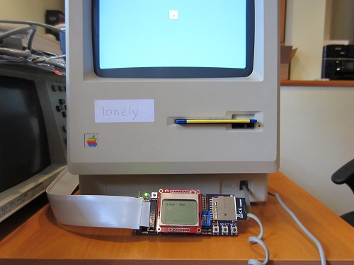
For those who may have missed the earlier progress updates, Floppy Emu is a floppy disk drive emulator for classic Macintosh computers like the Mac Plus. It plugs into the Mac’s DB-19 port, and behaves exactly like an external Sony 3.5″ disk drive would, so no special system software or other modifications are required. Floppy disk images are stored on a standard SD memory card, and a microcontroller (Atmel ATEMGA1284P) and CPLD (Xilinx XC9572XL) are used to read/write the floppy data. The data is converted into the GCR-encoded serial pulse stream that the Mac expects, exactly like the signal from a magnetic read head flying across a track on a real floppy disk.
The Floppy Emu prototype was constructed on a breadboard, using whatever parts were on hand. The prototype demonstrated 100% successful read emulation of an 800K floppy disk, and partially successful write emulation, depending on the type of write operation and the specific SD memory card used. The new Floppy Emu board shown here uses a more powerful microcontroller and different type of CPLD, and combines everything onto a single custom-made circuit board that fits right into the back of the Mac at the external floppy port. Power is provided by the Mac too, so there’s nothing to do but connect it and go.
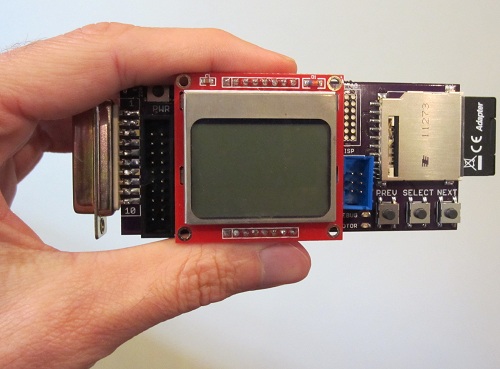
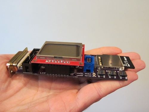
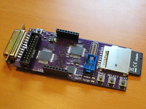
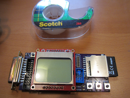
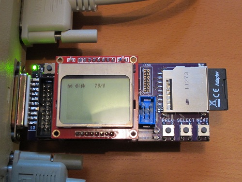
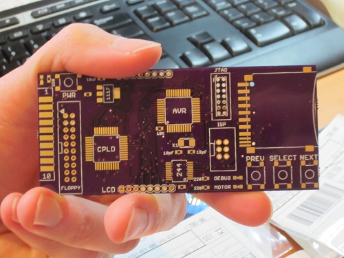
These photos show how small the Floppy Emu board is: about 1.75 inches wide and 4.5 inches long, including the DB-19 connector. The SD memory card extends an additional 0.5 inch beyond the end of the board. A roll of Scotch tape is also shown as a size reference. The Floppy Emu board is purple, but in most of the photos you’ll also see an LCD display on a red daughterboard. The LCD daughterboard is socketed, and can be connected and disconnected as needed. It’s the same Nokia 5110 LCD board sold by SparkFun and other several other vendors.
Thanks to its small size, the board fits nicely at the rear of the Mac, right between the mouse and the SCSI connector (or mouse and serial port on older Macs without SCSI).
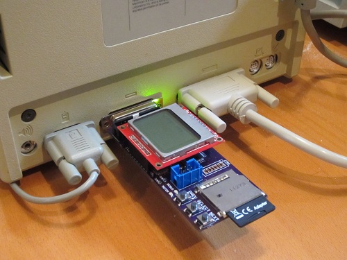
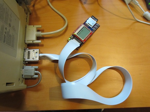
In addition to plugging straight into the external DB-19 floppy port, Floppy Emu can also be connected using a rectangular 20-pin IDC connector. This is the same connector found on the Mac motherboard, so a standard IDC cable can be used to connect Floppy Emu internally instead of at the external floppy connector. A DB-19 to IDC-20 adapter cable can also be used, such as the Apple II cable from IEC shown below. The cable enables Floppy Emu to connect to the external floppy port at the Mac’s rear, but positioned in the front of the Mac where it’s easier to use.
Everything is looking good so far. The next step is to program the CPLD, so communication with the Mac can be performed. The Floppy Emu board has a Xilinx JTAG connector at the upper-right of the LCD daughterboard, but it’s not populated and I’m hoping not to use it. Instead, my plan is save the CPLD configuration file on the SD memory card, and then use the microcontroller to configure the CPLD using a bit-bang JTAG method described in Xilinx app note XAPP058. Once that’s done, the final step will be to use the more powerful microcontroller on this board (as compared with the prototype) to experiment with new write emulation methods, and hopefully achieve 100% success for emulated floppy disk writes as well as reads.
Read 17 comments and join the conversation
Ready to Assemble
It took longer than I’d expected, but all the parts needed to build three Floppy Emus have finally arrived! That’s three custom-made circuit boards from Dorkbot PDX, plus the SD card sockets, CPLDs, AVRs, and a whole pile of buttons, LEDs, and other components. Now it needs some soldering love.
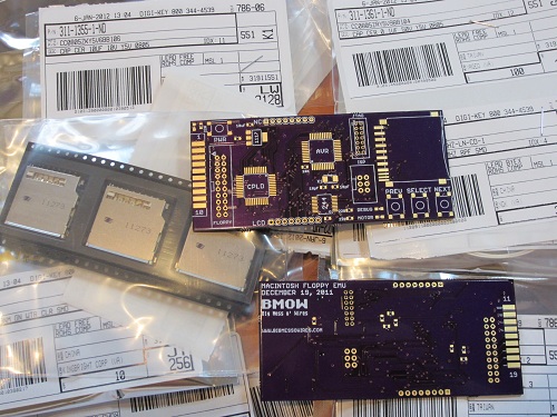
The boards from Dorkbot are as high-quality as ever: well-centered drills, crisp silkscreen, gold-plated pads, proper via tenting, and everything else. Unfortunately my last few Dorkbot PCB orders have been slower than normal to arrive. Even when I submit my design on the night before the deadline, the total end-to-end time from submission to boards in my mailbox is no faster than from a Chinese PCB maker delivering via China post. It’s about 17 calendar days in either case. With manufacturing done in the USA, one of Dorkbot’s big advantages is supposed to be turn-around time, but in practice it’s more a question of a higher price for a higher quality board than any question of time. I don’t mean to harp on Dorkbot– the guy who runs the PCB order is very nice, and I’m pretty sure he sinks a ton of his time into it while earning almost zero profit. I only wish it could be a little faster.
Now for the bad news: my enthusiasm for putting this board together seems to have evaporated. My hobby efforts come in waves, and I was very busy on this project in November and December, but now I can’t quite get excited about it. It’s not simply a question of soldering on the parts– I also need to modify the AVR firmware to use the ATMEGA1284 instead of the ‘328 from the prototype, implement indirect CPLD programming, and then implement the write buffering mechanism I keep talking about. I’m sure I’ll get to it soon enough, but right now when I look at the bare board, my mind wants to go read a book or go for a hike rather than jump into assembly. I’ve learned to listen to those voices, else a hobby can turn into a chore and cease to be any fun.
Read 8 comments and join the conversation
Parts Order By Mail

Today I ordered the parts needed to build three Floppy Emu boards, the Macintosh floppy disk drive emulator. Everything should be here by next week, so I can start building! In these small quantities, the total cost for the parts is about $47 per board, which is a lot more than I’d hoped. If I ever sell assembled Floppy Emus, they’ll probably need to have a retail price over $100 to cover the cost of assembly, testing, packaging, and a small profit to make it worth the time required.
In addition to being a “real” device instead of a hand-wired breadboard prototype, the new board will also use different parts than the original. The biggest change is the switch to an ATMEGA1284P AVR microcontroller, which has 16K of internal RAM to allow experimentation with different write buffering strategies. The CPLD is different too, with a Xilinx XC9572XL replacing the Altera-powered module that I scavenged from Tiny CPU for prototyping use.
Although the board has a footprint for a Xilinx JTAG header, I didn’t actually order the header, nor do I own a Xilinx JTAG programmer. I’m counting on programming the CPLD indirectly via the microcontroller, using the method described in Xilinx app note 058. If I can’t get that to work, I’ll have to go back and buy the header and a Xilinx programmer, which will mean more delays and more money. I’m keeping my fingers crossed that the indirect programming method turns out OK.
Read 12 comments and join the conversationFloppy Emu Board Layout
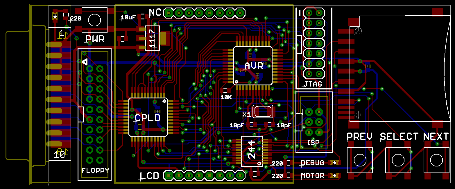
Whew! It took me a long time to do the board layout for the floppy disk emulator, but here it is! The board is about 4 x 1.75 inches, or roughly the size of an elongated credit card. The resistors, LEDs, and odd-sized capacitors are all labeled, so any other small rectangular surface-mount parts you see are 0.1 uF decoupling capacitors. Assuming nobody sees any problems, I’ll be sending this off to be manufactured in a few more days.
The AVR microcontroller used is an ATMEGA1284P, with 16K of internal RAM, running at 20 MHz with 5V. It replaces the ATMEGA32u4 breakout board used in my breadboard prototype. The CPLD is a Xilinx XC9572XL, which replaces the Atmel board from the prototype (which itself was salvaged from an old Tiny CPU project). The CPLD runs at 3.3V, but has 5V tolerant inputs. A 74LVC244 performs 5V to 3.3V level conversion. Sitting on top of the chips is a Nokia 5110 graphical LCD.
There are several options for connecting the Floppy Emu board to the Mac. The board has a male DB-19 connector as well as a male rectangular 20-pin IDC connector (the internal floppy connector on the motherboard). So you can:
- Plug the board straight into the Mac’s external DB19 floppy port. Then it will hang off the back like a dongle.
- Use an Apple II Unidisk/DiskII DB19 to 20-pin IDC cable, like this one from IEC. Connect the DB19 end to the external floppy port, and the IDC end to the Floppy Emu board. I purchased one of these and tested it to confirm that is has all the necessary connections.
- Use the DB19 to 20-pin IDC cable from an external Apple 3.5 inch floppy drive.
- Unplug your internal floppy drive, and use the existing internal floppy cable to connect to the board’s IDC connector. I’m not sure that cable is long enough to reach outside the case, though.
- Same as above, but use a longer 20-pin IDC cable. You can use any generic IDC cable with straight-through wiring.
After some consideration, I included both the 6-pin AVR ISP programming connector, and the 14-pin Xilinx JTAG programming connector. My goal is to use the AVR to program the Xilinx CPLD, so the JTAG connector is just there as a fallback. The JTAG interface consists of 4 pins: TMS and TDO are connected to dedicated pins on the AVR, but the TCK and TDI pins are shared for other purposes, since there aren’t enough pins for everything. The CPLD’s JTAG controller should stay in the reset state as long as the value of TMS is held at 1, regardless of what values appear on TCK and TDI, so in theory this should work fine. We’ll find out soon!
Initial programming of the AVR will be done using the 6-pin ISP connector and an AVR ISP mkII programmer. It should be possible to do all further AVR reprogramming using a bootloader, loading the new firmware from the SD card. That means if I build one of these boards for someone else, I can do the initial programming, then they can update the AVR firmware later by just storing an update file on the SD card and rebooting the emulator. They won’t need to own an AVR programmer. And since the AVR will program the CPLD, that means the complete firmware of both chips can be updated without the need for any special programming hardware. That’s pretty cool.
Read 15 comments and join the conversationThree Crazy Ideas
While I’m optimistic that the floppy write emulation technique described yesterday will work (at least for high speed cards), it would be great if I could buy an extra safety margin of time, or find a way of throttling the incoming data from the Macintosh during a write if it’s too fast. The biggest challenge is emulating the initialization of a floppy, where sectors to be written arrive from the Mac rapid fire, without stopping. Here are three slightly crazy ideas that just might work to handle the firehose of incoming data.
Floppy Driver Patch
One possibility is to write a custom INIT or extension that patches the floppy driver code in ROM, and extends the track step timeout from 12 ms to something much longer. This would be a simple change of just a few bytes, and it would enable the emulator to pause the incoming data after each track step, while it saved the previous track’s data to the SD card. Because there’s no problem with the speed of floppy read emulation, the INIT itself could still be loaded from the emulated floppy.
The major drawback of this approach is that it would force you to boot from a special Floppy Emu setup disk in order to load the INIT. I also don’t know anything about writing INITs and extensions, and I’m not sure if many different versions would be needed. Can the same INIT work with System 1.0 and System 9?
Faking An Error
In yesterday’s post, I said there’s no error mechanism that can be exploited to slow down the incoming data without causing the write operation to fail. I took another look at it today, and I think I may have found a way, by exploiting some code that measures the size of the gap between the last sector and the first sector on one side of a track. During initialization of a floppy, after the Mac finishes writing the last sector on a side, it immediately switches back to read mode to measure the gap before the next sector, and confirm that the next sector is sector 0.
The disk initialization code uses some kind of progress counter that starts with a value of 7. Every successful side written increments a counter by 1. If the gap is the wrong size, the counter is decremented by 1. If the counter value is greater than 4, it attempts to rewrite the side again, otherwise it aborts with an error.
By intentionally generating a bad gap size after a full side is written, I can force the side to be rewritten. If I also make the emulator smart enough to detect when data written to a sector is identical to what was already there, then it can ignore the second rewrite. That effectively doubles the amount of time available for saving the track data to the SD card, since every side will be written twice by the Mac.
The bad gap size trick can only be done once per side, or else the progress counter will decrease and the initialization process will eventually fail, so it can’t buy an indefinite amount of additional time. It’s also a little risky, because it means the progress counter will never increase above 7, and any 3 other errors occuring during the initialization will cause it to fail.
I did some simple tests of this idea that look promising. By disabling SD saves, I was able to perform floppy initialization to measure its write speed, even though the initialization ultimately failed during the verify phase. In my initial test, it took 34 seconds to complete the write phase of initialization. After I added emulator code to generate a bad gap after every other side write operation, the time increased to 59 seconds, with no obvious ill effects.
Zero Flag
During floppy initialization, the Mac writes 1600 sectors very fast. What’s in those sectors? Zeroes. Instead of buffering a 512 byte sector full of zeroes, I could just set a flag that says “this sector is all zeroes”. Using a bitfield, I could buffer an entire disk’s worth of zero sectors using just 200 bytes of RAM. Those sectors could then be saved to the SD card whenever it was convenient, after the floppy initialization was finished. If a read request arrived before all those zero sectors were saved to the card, the emulator could check the flag first to see if an all-zero sector should be synthesized instead of actually loading the sector data from the SD card.
I like this idea because it’s short and simple, though its usefulness is limited to floppy initialization only.
Read 5 comments and join the conversation