

Archive for the 'Floppy Emu' Category
Floppy vs SD Card Write Speeds
Which would you guess supports faster write speeds: a modern high-speed class 10 SDHC Flash memory card, or a vintage 1984 floppy disk employing a mechanical stepper motor to move its drive head, spinning magnetic media at a lazy 400 RPM? For large writes of contiguous blocks, the SD card’s speed blows the floppy away. But for random single block I/O, or sequences involving many alternating reads and writes, the SD card struggles to match the performance of the lowly floppy. That’s not a great thing to discover when you’re halfway through designing a floppy disk emulator.
Let’s put some numbers on performance. The floppy can read or write a 512 byte sector in 12 ms, with no variability: the speed is always one sector per 12 ms. An 8GB PNY class 10 microSDHC card in SPI mode can read a 512 byte block in about 2-3 ms, with a 4 MHz SPI clock. The same card exhibits single block write times of typically 5-9 ms, but with occasional spikes up to 70+ms for a single block. Write times appear to be inherent in the card, and mostly unrelated to the SPI clock rate. So while the average write speed of the SD card is somewhat faster than a floppy, the speed is variable, and the worst case is slower than a floppy.
Class 10 SDHC Emulator Results
The good news is that the class 10 SDHC card is fast enough to support emulation of normal floppy writes, in which some number of sectors on an existing floppy are updated. I’ve been able to copy large files around on the emulated floppy disk reliably, using the new class 10 card. This type of write actually follows a read-write-read-write pattern, as the Mac alternately reads to find the address section of the desired sector, then writes to replace the sector’s data section. Following each write, the emulator takes 5-9 ms to write the data to the SD card, while supplying sync bytes to the Mac. The Mac sees this as an extra-large intersector gap while attempting to read the next address section. It will tolerate gaps of up to roughly 23 ms, although this will make writing files noticeably slower than a real floppy.
The bad news is that the class 10 SDHC card is not fast enough to support emulation of continuous floppy writes, such as those during initialization of a floppy, or when doing a full-disk write with a disk copy program. This type of write is just a constant stream of incoming bytes, at a rate of one sector per 12 ms. The emulator cannot stall after the first sector to peform an SD write, because the second sector is already inbound. To address this I implemented a double-buffered system, which uses an interrupt routine to read the next sector’s data into a new buffer, even while the data from the old buffer is being written to the SD card. Unfortunately, the overhead of the interrupt routine increases the SD write time to 12+ ms, so the emulator simply can’t keep up with the incoming data. Using more than two buffers might help, if there were enough RAM for them, but the average SD write time would still need to be under 12 ms. Buffering helps recover from occasional “burps” where a write takes longer than 12 ms, but it can’t improve the overall write speed.
Incidentally, while studying continuous write behavior, I discovered that sectors in a Macintosh floppy track are interleaved like 0 6 1 7 2 8 3 9 4 10 5 11, rather than being appearing in consecutive order by sector number.
Arrgh!!
This whole business of emulator write support is turning into quite a pain, causing the fun value of the project to drop steeply. To make matters worse, I somehow managed to brick the class 10 card while I was experimenting with raw SD block operations, and I don’t have any device that will reformat it. As much as write support is an essential part of floppy emulation, I’m questioning how much more time it makes sense for me to sink into it. I’m therefore tempted to eliminate write emulation entirely, release a design for a read-only floppy emulator, and leave it at that.
My brain is struggling with the details of card performance in single-block and multi-block write modes, various buffering schemes, and timeout values for Macintosh I/O operations. My gut tells me there must be some clever way to use buffering and/or multi-block writes to get reliable write performance, even with a slow SD card, but so far I haven’t found a solution. And regardless of any amount of buffering or other clever schemes, I believe that if any single block write takes more than about 12 ms (the max track step time) + 23 ms (the max intersector delay), then emulation could fail. The computer might do a write immediately followed by a track step and then a read, which couldn’t be serviced until the write finished.
I looked again at the HxC Floppy Emulator, which uses a PIC and a 32K SRAM to emulate floppies for other classic computers. The author has been kind to answer many of my questions about its inner workings, but I don’t know the buffering strategy it uses, or whether it’s subject to failure in the same worst cases as my design.
Write Options
Some other possibilities, short of eliminating write support completely:
Experimental Write Support – I could leave the write emulation as it is now, and call write support “experimental”. It would be a crap shoot whether it worked or not, depending on the card that was used. I think normal writes from Finder file operations would work on most class 10 cards, but continuous writes (disk initialization and disk copying) wouldn’t. Maybe that’s acceptable.
Strict Card Requirements – The author of SdFatLib ran one of my performance tests, and got substantially better write performance using two different models of SanDisk Extreme cards than I saw on my class 10 PNY card. Unfortunately my local store didn’t have any high speed SanDisk microSDHC cards. If those cards work reliably, I could make them “required” for write support, but I’m uncomfortable with that idea. Even if it worked, I wouldn’t be any closer to understanding why some cards work and some don’t. I’d also be faced with the task of continuously testing new cards as the old SanDisk ones were obsoleted and replaced with different models.
Multi-Sector Writes – Instead of single block writes, I could use the SD multi-block write method. Using this method, you tell the card “I’m writing N blocks beginning at location L”, and it pre-erases all the blocks, then writes them quickly as they arrive. This makes individual block writes much faster, but requires the pre-erase step, and also requires knowing how many blocks you’re going to write before you write the first one. That’s not possible when writing blocks as they arrive from the Macintosh, since it’s never known when the floppy write will end. If many sectors were buffered in RAM first, then they could be written in a multi-block write, but the length of the multi-block operation would present its own challenges. What would happen if during the long multi-block write, the Mac decided to step to a different track and begin reading new sectors?
A related method I’ve yet to try is to erase the SD block as soon as the data for it begins to arrive from the Mac, instead of waiting until the entire sector is received from the Mac before doing an SD erase and write. I’m not even sure that’s possible, but it seems like it would help.
Code Optimization – I believe that continuous writes with the class 10 PNY card are falling just short of the necessary average speed. If I could optimize the interrupt routine to reduce its overhead, it might work. Without substantial buffering, however, continuous writes would still fail whenever there was a single anomalous slow write, even if the average write speed were fast enough.
More RAM Buffering – By using an AVR with more internal RAM, I could buffer more sectors during writes. That feels like it should help somehow, but I’m not certain it actually would. With my current code, normal writes don’t use buffering. The class 10 card doesn’t need buffering, since the SD write is performed during the intersector gap before the next read. The class 4 card I tested earlier had such strange latency patterns (12 consecutive writes of 50-80 ms) that no amount of buffering would help it. In fact, buffering would provide no benefit, because a second write from the Mac cannot begin until the first write to the SD card finishes, the next sector is read from the card, and the Mac reads that sector’s address section.
Additional buffering would help somewhat with continuous writes, if they can be optimized enough so that their average write time is fast enough. A large buffer could also be used to read a full track into RAM at once, then play the tracks from RAM instead of continuously reading them from the card. That would enable SD writes to happen without blocking SD reads of sectors in the same track. However, a similar blocking problem would still occur if the Mac stepped to a different track and began to read sectors there, while a long SD write operation was monopolizing the card.
Buffer the Whole Disk – The extreme of buffering is to use 800K of external SRAM to buffer the entire disk. Maybe that’s a sensible idea, and it would certainly work, but I’m very reluctant to do it. Aside from the additional pins needed and the cost of the parts, it just feels wrong. HxC is proof that floppy emulation should be possible without a full disk buffer.
Whew!
Documenting the possible options here has been an exercise in organizing my own thoughts, more than an attempt to explain them to others, so I hope it’s comprehensible. It’s starting to feel a bit like I’m launching into a graduate thesis project! That’s not a good sign, and I’m concerned I’ve already spent more time experimenting with write support than makes sense. Once I (hopefully) unbrick my class 10 SD card, I’ll try a few more experiments to see if I can improve write performance further. But after that, I think I’m going to return to the hardware design, and plan to use an ATMEGA1284P with 16K of internal RAM. Any further improvements to write emulation will then have to be done entirely in firmware, within the limitations of that hardware.
Read 13 comments and join the conversationSD Write Speed Anomolies
I have floppy disk write emulation almost working for Floppy Emu, using an almost painfully simple technique. When the Mac sends data to be written, an interrupt routine decodes it and stores it in a RAM buffer. Once a full sector has been stored, the main code path performs a blocking write to the SD card. If the Mac attempts to read the floppy during this time, it will see nothing but sync bytes. If it attempts to do another write, the write will be ignored.
This method works because the Mac doesn’t actually write a whole string of sectors at a time. Instead, it performs an alternating pattern of reads and writes for each sector. It reads the disk, waiting until the address section for sector N passes the drive head. Then it switches to write mode, and overwrites the data section for sector N with new data. After the write, it switches back to read mode and looks for the address section for sector N+1. The string of sync bytes provided by Floppy Emu while it’s writing the SD card is interpreted by the Mac as a normal (if unexpectedly long) intersector gap.
Using this method, I’ve successfully performed one-sector writes with a test app. I’ve also had some success copying larger files (50-100K) onto the emulated floppy with the Finder– sometimes it works, sometimes not.
While investigating why the writes sometimes fail, I discovered something strange. With my microcontroller at 16 MHz and a 4 MHz SPI clock, using SdFatLib to write a single aligned 512-byte block normally takes 3-7 milliseconds. That’s fast enough to keep the Mac happy. But I’m seeing a consistent pattern where after 8N consecutive blocks written, the write time jumps to 50-80 ms per block for the next 12 blocks, then returns to normal. In other words, it will write some multiple of 8 blocks at 3-7 ms per block, then write the next 12 blocks at 50-80 ms per block, before returning to the original 3-7 ms speed. 50-80 ms is too slow for the Mac, so it aborts, and the write operation fails.
In most cases N=4, so the strange behavior begins after 32 blocks. This seems to be true no matter what portion of the SD card file I write into, for consecutive sectors in both increasing and decreasing order. The code is (roughly):
	// time some writes at a random position within the file
 	uint16_t sect[100];
	uint8_t time[100];
	for (uint16_t s=900, c=0; s<1000; s++, c++)
	{
		uint32_t writePos = s * SECTOR_DATA_SIZE;
		f.seekSet(writePos);
		uint32_t t1 = millis();

		// save the sector
		if (f.write(sectorBuf, SECTOR_DATA_SIZE) != SECTOR_DATA_SIZE)
		{
			// write error
		}
		uint32_t writeTime = millis() - t1;

		sect[c] = s;
		time[c] = writeTime;

		_delay_ms(5);
	}
This may well be a problem with my SD card, or something strange about SdFatLib, but I’m unsure where to go next to troubleshoot it further. None of the write methods I’ve looked at will tolerate 50-80 ms write times, short of buffering the entire 800K disk image in an external RAM. The consistency of the 8N fast blocks followed by 12 slow blocks makes me suspect some kind of cache or buffer somewhere is filling up. But then I would expect all further writes to be slow, instead of returning to normal speed after 12 slow writes.
Read 7 comments and join the conversationViolating Setup Times With Floppy Writes
I’m working on adding write support for the Floppy Emu emulated Macintosh floppy drive. Data coming from the Macintosh to be written to the floppy is encoded in an interesting way. There’s no clock signal, but just a single WR data signal. The incoming WR data is divided into bit cells of “about 2 microseconds” duration, according to the IWM datasheet. At each bit cell boundary, a high-low or low-high transition indicates a logical 1 bit, and no transition indiciates a logical 0 bit.
This technique presents some challenges to the device that’s decoding the WR data. Without a clock, how does it know when to sample the data for the next bit? And without some kind of framing reference, how does it identify the boundaries between bytes?
Instead of sampling bits at some fixed frequency, my solution uses 16x oversampling to measure the duration between WR transitions. A measured duration of about 2 microseconds (with some error tolerance) is interpreted as a 1, about 4 microseconds is 01, and about 6 microseconds is 001. Durations longer than 6 microseconds should never appear, since the GCR encoding method forbids having more than two consecutive 0 bits.
To identify the boundaries between bytes, the circuit uses the fact that all valid GCR bytes have a most significant bit of 1. If the MSB of the shift register is 1, it saves the completed byte, and clears the shift register. Assuming it starts at a random location in the bit sequence, the circuit will eventually sync up with the byte boundaries correctly, but it may take many bytes before it syncs correctly. Fortunately the Apple designers planned for this, and each sector begins with a string of 10-bit sync bytes 1111111100. No matter where it starts in the sequence, a shift register using this byte indentifiaction technique will get in sync after no more than five sync bytes.
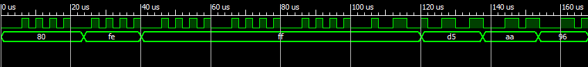
The waveform above shows a simulation of the start of a sector, consisting of five sync bytes followed by D5 AA 96, the sector header identifier. The top trace is the WR signal, and the bottom trace is the output of the shifter/decoder circuit. Here’s my first version of the Verilog code, using an 8 MHz input clock, where 16 clocks equals 2 microseconds.
reg [7:0] shifter;
reg [7:0] wrData;
reg [4:0] bitTimer;
reg wrPrev;

always @(posedge clk) begin
  // was there a transition on the wr line?
  if (wr != wrPrev) begin
    // has at least half a bit cell time elpased since the last cell boundary?
    if (bitTimer >= 8 ) begin
      shifter <= { shifter[6:0], 1'b1 };
    end
    // do nothing if the clock count was less than 8

    bitTimer <= 0;
  end
  else begin
    // have one and a half bit cell times elapsed?
    if (bitTimer == 24) begin
      shifter <= { shifter[6:0], 1'b0 };
      bitTimer <= 8;
    end
    else begin
      // has a complete byte been shifted in?
      if (shifter[7] == 1) begin
        wrData <= shifter; // store the byte for the mcu
        shifter <= 0; // clear the byte from the shifter
      end

      bitTimer <= bitTimer + 1'b1;
    end
  end

  wrPrev <= wr;
end
I implemented the circuit as above, and it mostly worked. The output was recognizably close to what was expected, but with lots of seemingly random bit errors. The errors weren’t consistent, and comparing the output to the expected values, the errors didn’t appear to be systematic either. I was hoping that they might all be cases of a 0 turning into a 1, or all cases of a 1 turning into a zero, or all cases of a single bit being added or removed in the sequence, but it was nothing like that. I couldn’t find any identifiable pattern to the errors at all.
A day passed. I chased after theories involving voltage levels, bus contention, poor wiring, and others.
Finally I got to thinking about the timing relationship between the WR signal and the 8 MHz clock– there is none. I should have realized this earlier, since it’s nearly the same problem I had a few weeks back with the LSTRB signal when I was implementing read support. WR might transition right at an 8 MHz clock edge, so that its sampled value is neither a clean logical 0 or 1, but somewhere in between. What happens then?
Naively, I had thought it would either do the 0 behavior, or the 1 behavior. In this example, it would either do the first if block and add a 1 to the shifter, or else it would do the second if block, and check the timer to see if it should add a 0 to the shifter. It wouldn’t really matter which behavior it did– a transition on WR would either add a 1 to the shifter on clock cycle N or N+1, but it would still get added. The test for bitTimer >= 8 would make sure that an apparent double-transition of WR didn’t accidentally add two 1’s. Everything would work great.
If only it were so simple. The registers bitTimer, shifter, and wrData are composed of many individual macrocells in the CPLD, one macrocell per bit. Each macrocell will decide independently if wr != wrPrev at the clock edge. What happens if they don’t all agree, and some macrocells think there was a transition, and others don’t? You get a big mess of random errors, which is exactly what I was seeing. This is why a synchronous system would impose a setup time on WR, to make sure its value was established long enough before the clock edge to ensure that every macrocell saw the same value. This isn’t a synchronous system, though, and there’s no way to guarantee that WR won’t change states at a bad time.
Fortunately the solution is simple: just send WR to a register, then use the register value in the circuit instead of WR. That means the circuit will be using a value of WR that’s delayed one clock from the “live” value, but that’s not a problem here. Because the value of the register will only change at a clock edge, the circuit that uses the value won’t see it change states at a bad time, and setup time requirements will be met. This technique is probably second nature to many readers, who’ve been shouting at their monitors for the past six paragraphs, but it took me a while to figure out. The code changes look like this:
reg [1:0] wrHistory;

always @(posedge clk) begin
  // was there a transition on the wr line?
  if (wrHistory[1] != wrHistory[0]) begin
    // ... remaining code is the same as before

  // ...

  wrHistory <= { wrHistory[0], wr} ;
end
With that change, I’m now able to reliably parse floppy write data coming from the Mac. Next up: reading the data with an interrupt routine, and saving it to the SD card.
Read 6 comments and join the conversation
Implementing Floppy Emu Writes
I’ve yet to implement write support for my SD card Macintosh floppy emulator, but my rough plan was:
- Perform GCR decoding on the fly, and store decoded sectors in RAM
- When the Macintosh steps to the next floppy track, use the delay to flush the sector data to the SD card
- Need to buffer as much as both sides of a 12-sector track, for 24 total sectors, or 12288 bytes
- Use a microcontroller with at least 12K RAM for buffering
Too Slow
For this to work, the microcontroller and the SD card must be fast enough to write 12288 bytes during the track step time. On a real floppy drive, the step time is about 4 ms, but in my tests it can be as long as 12 ms before the Macintosh aborts with an error. 12288 bytes in 12 ms is 8192000 bits/second, so the SPI clock used for SD card communication must be at least 8.192 MHz. On the ATMEGA series, the SPI clock can be at most half the CPU clock speed, so the minimum CPU clock speed would appear to be 16.384 MHz.
But wait, it’s worse than that, because SPI communication isn’t 100% efficient. There’s a delay between each byte, while the microcontroller checks to see if it’s time to send a new byte, and then queues it up. There’s also a delay between each 512 byte block. And if the disk image file being written doesn’t occupy consecutive blocks on the SD card, there will be additional delays between each block, as the SdFatLib code uses the FAT info to locate each block of the file. My rough guesstimate is that actual performance would be 50% to 100% slower than predicted by the SPI clock speed, and that matches the numbers I’ve seen from other people using SdFatLib. To compensate, the CPU clock would need to be 50-100% faster, around 24 MHz to 32 MHz.
A further complication is that the entire 12 ms step window can’t be used for SD writes. Some of that time is needed to update the LCD display, and other housekeeping tasks needed when stepping tracks. To compensate, the CPU clock would need to be still higher.
In short, this approach to writes is simply not going to work on an ATMEGA microcontroller with a maximum clock speed of 20 MHz.
Go Faster
One solution would be to use a different microcontroller that supports higher clock speeds, like an ARM series mcu that was suggested by commenters in the previous post. That would probably work, although I’m reluctant to do it, since it would entail redoing much of the design, learning the details of a new architecture, porting the code to it, and getting programming hardware for the new mcu.
I’m also uncertain how fast the SD card can actually go over SPI, and I haven’t found any definitive answer. The number 25 Mbps appears in a few places, but I think that’s using the multi-bit native SD interface rather than the 1-bit SPI interface. Regardless of the SD card’s capabilities, if I push the SPI clock speed higher, I’ll need to design a circuit board that works well at high clock speeds, which means paying attention to all the board layout details I don’t fully understand and normally ignore. I think I should probably be okay at speeds of 10-20 MHz, but I’m really not sure.
Background Writes
A more complex solution that doesn’t rely on increased clock speeds is to perform SD card writes in the background, while data is being transferred from the Macintosh, instead of trying to squeeze the SD writes into the track step interval. This was suggested by a commenter in an earlier post, and while it would be trickier to implement, it has many advantages.
This method would only require two sector buffers, for 1024 total bytes of RAM. As the Mac sent the data for the first sector to be written, the microcontroller would decode it and store it in RAM buffer 0. After the last byte of the sector’s data was received, the mcu would immediately call an SdFatLib function to write the sector data to the SD card, but it would also install an interrupt handler to be invoked when bytes were received for the next sector. The interrupt handler would store these in RAM buffer 1. The SD write of the first sector would complete well before the last byte of the second sector was received. SdFatLib would then be called to write buffer 1 to the SD card, while the next sector’s data was being stored in buffer 0 by the interrupt routine. In this way, the mcu would always be writing one buffer to the SD card while the interrupt routine filled the other buffer with data for the next sector.
This approach is appealing because it doesn’t require especially fast clock speeds, nor does it require a microcontroller with a large amount of RAM. In fact, it would probably work with the ATMEGA32u4 I’ve been using for breadboard prototyping, which has just 2K of RAM.
In order for this method to work, there must be sufficient time between each “new byte” interrupt to do the following:
- store the processor state and invoke the interrupt handler
- perform GCR decoding on the byte
- store the byte in the RAM buffer
- return to the main program, which is executing an SdFatLib write
- make sufficient progress on the SdFatLib write before the next interrupt so that the write finishes before the last byte of the next sector is received
The interrupt rate is fixed by the Macintosh’s floppy data rate, so the interrupt will be invoked every 16 microseconds. Depending on the ATMEGA’s clock speed, that’s enough for 128 to 320 clock cycles between interrupts. Is that enough to accomplish all of the above? Probably, but it might be a little tight.
Read 8 comments and join the conversationMixing AVRs, Xilinx CPLDs, and JTAG
I’ve been working on optimizing the Floppy Emu design in preparation for making a custom circuit board, and as always I’m faced with a dizzying number of choices and potential trade-offs. The design calls for a Xilinx XC9572XL CPLD along with an Atmel ATMEGA1284P AVR microcontroller, and I’ve belatedly realized that even the simple task of programming these chips will raise some problems.
Programming Connections
For starters, I don’t actually own a Xilinx JTAG programmer, and my Altera JTAG USB Blaster appears to be a single-purpose device, so I’ll have to purchase a new Xilinx programmer. Then I’ll have to cram both a 2×5 JTAG header (for the CPLD) and a 2×3 ISP header (for the AVR) into the board, which seems awkward and redundant. Is there a better way?
The ATMEGA1284P also supports JTAG programming, if you’re willing to give up use of four GPIO pins. I could use a single 2×5 JTAG connector, connect the two chips in a JTAG chain, and use JTAG to program both the microcontroller and the CPLD. But with what programmer? I don’t want to have to purchase a Xilinx JTAG programmer and the Altera AVR JTAG ICE Programmer. There must be a generic JTAG programmer that will work with them both, but I’m uncertain which one, and with what programming software.
Another option is to use the ATMEGA to program the CPLD somehow, by connecting the CPLD’s JTAG pins to GPIO pins on the ATMEGA. Then I’d only need a single 2×3 ISP connector for programming the ATMEGA, and could use the AVR ISP programmer that I already have. But I don’t relish trying to write a JTAG player for the microcontroller, and a brief search to see if something like that already exists didn’t turn up anything.
Voltage Levels and Clock Speeds
Initially I’d planned to run the ATMEGA with an external crystal at 16MHz. Unfortunately, to run at that speed requires a 5V supply, and everything else in the system will be using 3.3V, so level conversion will be required. Although it’s not a horrible problem, level conversion is one more headache that I’d prefer not to deal with. According to my squinting at the graphs in the datasheet, at 3.3V the ATMEGA should safely run at speeds up to 13.3MHz — call it 12MHz to pick a round number on the safe side. Or I could use the internal 8MHz oscillator, and dispense with the external crystal entirely, eliminating yet another part.
But in a system where I’m concerned that write performance may not be fast enough to keep up with the Mac, is it really a good idea to drop the clock speed from 16MHz to 12MHz or 8MHz? For that matter, why not increase the clock speed to the maximum of 20MHz? Or use a different chip like the ATXMEGA192, which has an internal 32MHz oscillator and runs at 3.3V?
The truth is I really don’t know what clock speed will be needed. I’m relatively confident that given a large RAM buffer for track data, reads will work at clock speeds of 8MHz or even lower. Writes are the concern– the Mac will pump out data sector by sector, with no flow control mechanism, so Floppy Emu must either keep up or fail. While the micrcontroller clock speed will clearly be important, the SPI clock speed used to communicate with the SD card is probably even more critical, and that can be varied independently. Furthermore, the reading I’ve done suggests that maximizing SD transfer rates has less to do with increasing the clock speed than with optimizing the transfer code, using multi-sector transfers where possible, and so forth. I’m not sure how well-optimized sdfat lib is in that respect. In the end, while it’s hard to argue against the “faster is better” sentiment, it’s unclear that a higher microcontroller clock speed is necessary or sufficient for making writes work.
Presently I’m leaning towards eliminating the level converter, running the microcontroller at 3.3V, and limiting the clock speed to 12MHz (or 8MHz with the internal oscillator). My reasoning is that the ATMEGA is likely to either be plenty fast enough to support writes, or not even remotely fast enough. Running at 5V with a level converter is only worthwhile if I believe the extra 66% speed bump going from 12MHz to 20MHz will be the difference between being too slow or just fast enough.
Read 6 comments and join the conversationMacintosh Floppy Emu Video
Here’s a brief video of Macintosh Floppy Emu in action, booting a Mac Plus from the emulated floppy, and then reading the floppy using Disk Copy 4.2.
Be the first to comment!