

Care Package
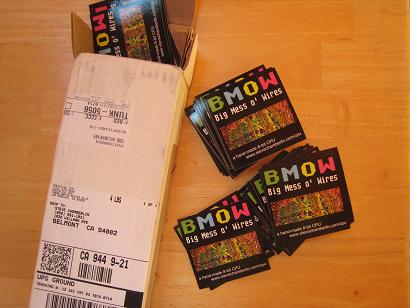
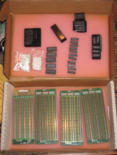 After reading about BMOW on Slashdot last week, Jim George offered up some Augat wire-wrap boards and old-school ICs that were sitting around gathering dust. His care package arrived today, just in time for a weekend of tinkering.
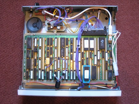
There are four Augat boards, each one about 7 x 2.5 inches, or about 25% of the area of the BMOW system board. Each board has space for five columns of skinny DIP 0.3 inch chips. The undersides (not shown) are pre-populated with about 600 wire-wrap pins.
Jim also threw in a few dozen wire-wrap tags, which are just little plastic cards with holes in them that can be placed on the pin side of the board, showing where the chips are placed and marking the pin numbers. I can’t believe I built all of BMOW without these. They seem like such an obvious thing. Staring at a featureless green board with a thousand pins on it, it’s easy to get disoriented without markers like these.
To round out the package, Jim also included a handful of 7400 series logic chips, and other related parts:
- 74AS181 x 5, 4-bit ALU
- 74ALS374 x 11, 8-bit register
- 74F323 x 7, 8-bit shift register
- 74F299 x 6, 8-bit shift register
- 6116 x 3, 2K x 8 SRAM
- Intel 8255 peripheral interface adapter
Thank you Jim!
Read 5 comments and join the conversationFillRect
OK, time to get back to 3D Graphics Thingy! 3D graphics rendering, implemented in hardware. Here we go. Starting right now. Any time now. 1, 2, 3, go. Getting ready, this is it, here we go. OK, really, going to start now.
I stared at a blank sheet of paper for a long while yesterday, and realized I have no idea what I’m doing. How do you make a digital circuit that draws stuff? Where do you even start?
Assuming I had some video memory, and a circuit to display the contents of video memory, I might implement a FillRect function in C like this:
void FillRect(int left, int top, int right, int bottom, int color) {
    for (int y=top; y<=bottom; y++) {
        for (int x=left; x<=right; x++) {
            memory[x][y] = color;
        }
    }
}
Taking this a little further, I could assume a screen width and height of 256 pixels, and one byte per pixel, for a total video memory size of 64K. That would enable me to directly use the X and Y coordinates of a pixel to determine its memory address, by using Y as the upper 8 bits of address, and X as the lower 8 bits. The revised C code would be:
void FillRect(uchar left, uchar top, uchar right, uchar bottom, uchar color) {
    for (uchar y=top; y<=bottom; y++) {
        for (uchar x=left; x<=right; x++) {
            memory[(y<<8)|x] = color;
        }
    }
}
Now how do you build hardware to do that? After more staring at a blank sheet of paper for a while, I started drawing things, and eventually came up with this:
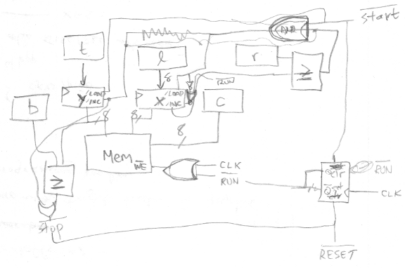
My scrawl is difficult to follow, so I cleaned it up in a drawing program. In the diagram below, the data path is drawn in blue, and the control path in orange. All the control signals are assumed to use positive logic for clarity (1 = active), although in a real circuit with real chips, most would actually use negative logic. The five blue boxes along the top are all 8-bit registers, something like a 74HC377. The two darker blue boxes for X and Y are 8-bit counters, like a 74HC393 maybe. For the counters, I assume that their load input takes priority over their count input, if both are asserted simultaneously. The two boxes labeled “=” are comparators that output true when their inputs are equal, like a 74HC688. The orange run box is a single flip-flop with synchronous set and reset inputs.
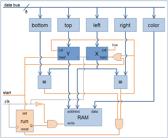
How does this work? Initially run is false, so the output of the AND gate connected to the RAM’s write input is also always false, and nothing gets written. To start things going, the CPU (not shown) writes the desired values to the bottom, top, left, right, and color registers for the rectangle to be filled, and then asserts start. At the next clock edge, three things happen:
- run is set to true
- Y is loaded from top
- X is loaded from left
Notice the clock signal itself is used as a control signal, connected through an inverter to the AND gate feeding the RAM’s write input. On the next clock cycle following start, during the second half when the clock signal is low, the output of the AND gate becomes true, and the value in the color register is written to the address specified by the X and Y registers. Oh my God, a pixel was just filled!
The X register’s count input is connected directly to true. At the next clock edge, X is incremented by one, and on the next clock cycle, the neighboring pixel one spot to the right is filled. This continues until X reaches the value stored in the right register, at which point the output of the comparator becomes true. This forces X to be reloaded with the value from left (load preempts count), and also increments Y by one, accomplishing a movement to the start of the next line.
Eventually the filling operation reaches the last pixel of the last line, when Y equals bottom and X equals right, and the output of both comparators becomes true. This resets the flip-flop, forcing run to false, and disabling any further writes to video memory. The FillRect operation is complete.
With work, this FillRect hardware could be generalized to FillTriangle hardware more similar to what 3DGT will need. If left and right were initially equal, and then incremented or decremented by a fixed step on each new line, then flat-bottomed triangles of any shape could be drawn. The per-line steps for left and right would be the inverse slopes of the triangle edges. To draw any general triangle without the flat-bottom limitation, the same circuit could be used again in reverse to draw a flat-top triangle connected to the first flat-bottom one. Alternatively, the hardware could be extended to draw the complete triangle directly, by adding a new knee register, and changing one of the line slopes when Y reaches knee.
Read 3 comments and join the conversationAftermath
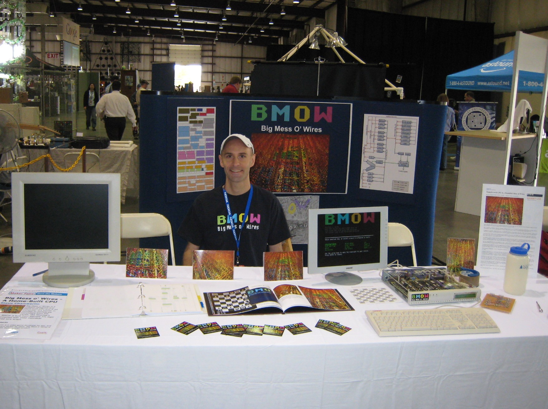
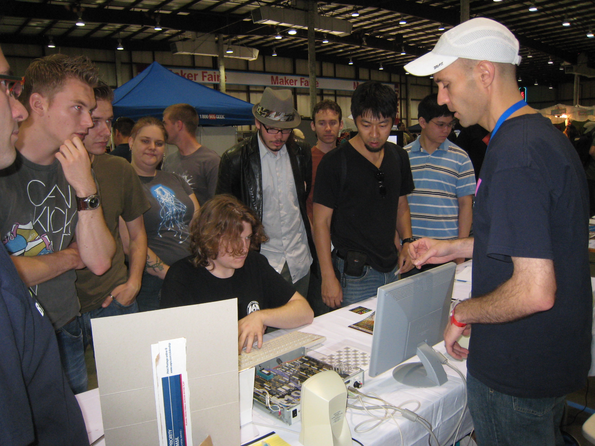
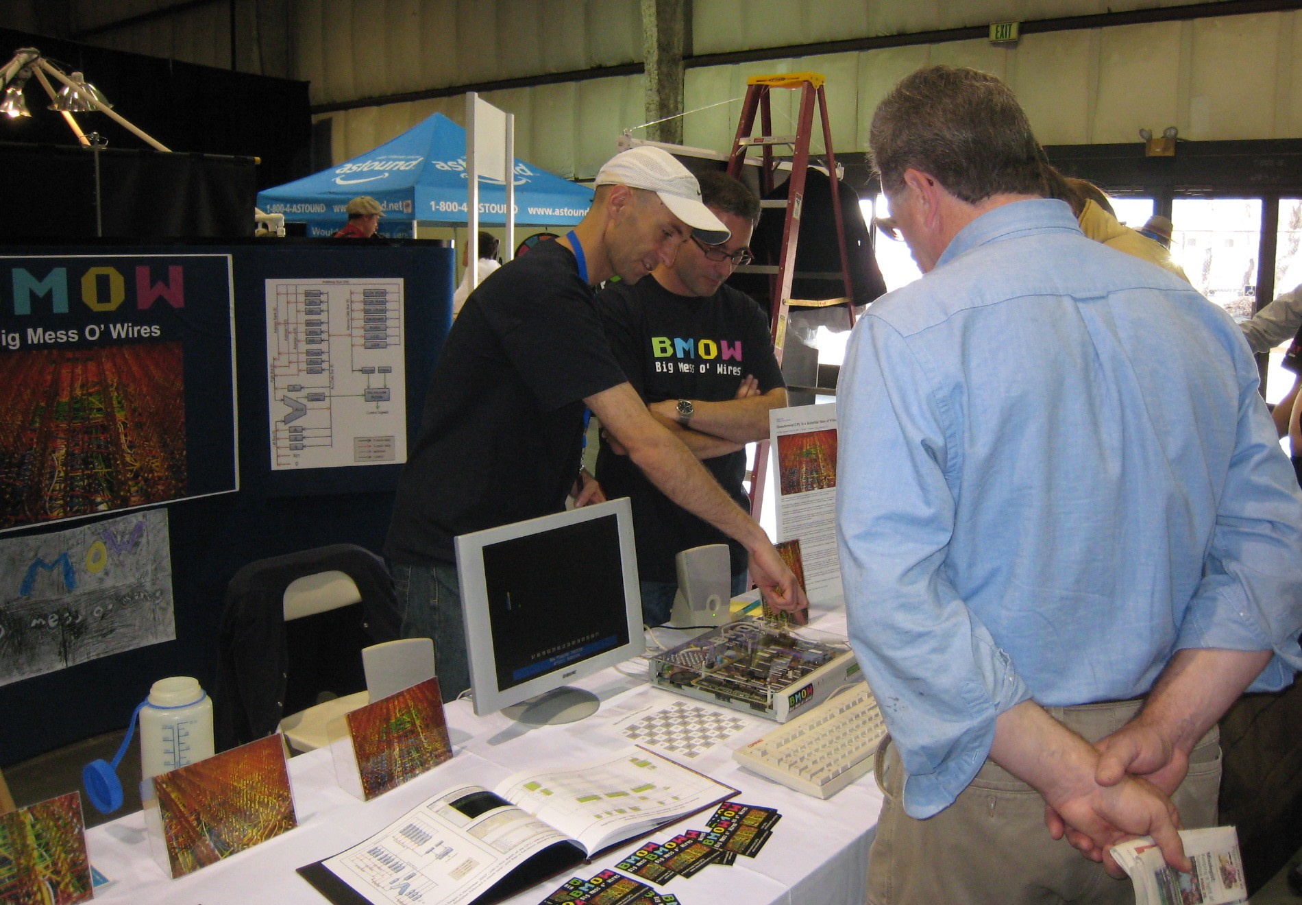
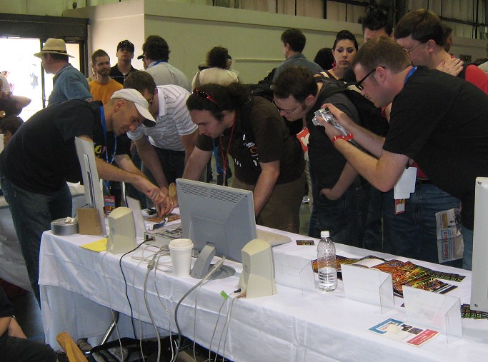
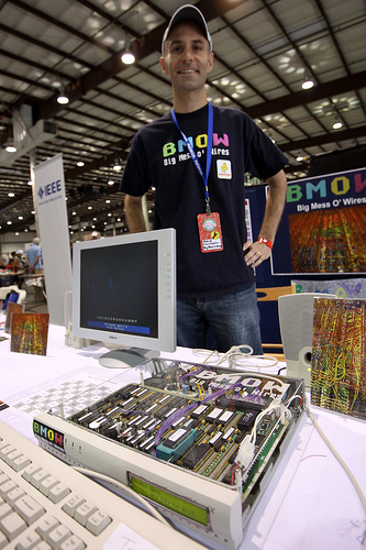 Photo by Joe Pankow Oh ye gods! Crazy, nutty, insane. The past few days have been among the strangest of my life. I think I’ve had my 15 minutes of fame and then some. First there was the article about BMOW 1 on Wired.com, then the story got picked up by CNet, Digg, Slashdot, Engadget, Gizmodo, Reddit, and many others, all over the web. My inbox overflowed with people asking about the project. Then came the Maker Faire, where a few thousand people came through the BMOW booth over a two-day period. People were amazingly enthusiastic, and quite a few people told me they came to the Maker Faire specifically to see BMOW! In the Wired article about “What to do at the Maker Faire“, BMOW was even the featured attraction for the entire event. In the end, it won an editor’s choice award for the show, and I talked myself hoarse.
While I appreciate all the attention this project has suddenly received, I have to admit I feel like a fraud. For one thing, Bill Buzbee’s fabulous Magic-1 homebrew computer was also at the Maker Faire, and it’s twice as cool as BMOW, but didn’t get nearly the press coverage. I also think that most of the people talking about BMOW thought it was something it’s not. A lot of people seemed to have the idea that I’d built a CPU entirely out of wires, as if wires themselves could perform computations. Or they thought I’d built some kind of giant machine the size of a refrigerator. When they saw a rather ordinary-looking 12 x 8 inch board at the show, they looked disappointed. Many people also seemed to have the idea that I’d built a CPU out of thousands of individual transistors. Nope. BMOW is made from sixty-five chips including 7400-series parts, 22v10 PALs, ROMs, SRAM, a video DAC, and an AY audio chip.
It was an incredible time at the Maker Faire. Setup began on Friday, so I was able to get in before the show opened to the public, and chat with some of the other Makers before the crowds arrived. The show is sprawling, massive: two giant expo halls, plus all the grounds between and around them, and half of an enormous parking lot. It was really too much to experience in a single day.
One downside of being a Maker presenting BMOW is that I didn’t get much chance to visit the other exhibits. Fortunately, I did have a chance to talk with a few amazingly brilliant people. I spoke to Jeri Ellsworth, creator of the C-One reconfigurable retro-computer (who was demoing DIY transistors), Limor “Lady Ada” Fried, inventor of all manner of Arduino and other electronic projects, and evilmadscientist.com’s Windell Oskay, who was demonstrating the Candy Fab 6000 sugar-based 3D printer. There were also many other amazing and creative people I spoke to, not all of whose names I caught, but it was great to get wrapped up in an aura of geeky achievements with them all.
Thanks to everyone who came by the BMOW booth at the Faire, and to my friends Kevin and Eric for helping out as BMOW crew members for the weekend. The booth was packed almost non-stop from open to close, both days. If I’d had the foresight to make extras, I could have sold a ton of books and T-shirts, and lots of people asked about them. Some people even asked about buying kits. I can only assume they had a spare year with no particular plans, and were looking to fill it. A few people came by the booth and gave me free stuff! A guy from Parallax gave me a Propeller development board. I’ll definitely have to play around with that.
A few questions about BMOW came up again and again:
- “What’s the operating system?” When I answered “there isn’t one”, this seemed to blow people’s minds. How could you have a computer without an OS? For BMOW the hardware is so simple, the programs themselves essentially *are* the OS.
- “What compiler did you use to write programs?” Some people seemed genuinely astounded that it’s possible for a human to write programs in assembly language. Whether they’re too young to remember when that was the norm, or have just spent too much time coding in Python or something, I don’t know. Yes, it’s all BMOW assembly language, which is mostly identical to 6502 assembly. I tinkered with retargeting a C compiler for BMOW, but never went very far with it.
- “Where are the wires?” Ah yeah. I supposed it’s false advertising to have a project called “Big Mess o’ Wires”, and not have a giant hairball of wiring hanging out somewhere. There wires are all hidden on the underside of the system board. Sorry.
In the end, BMOW won a Maker Faire Editor’s Choice award. In fact, it won one twice. I’m not really sure what happened there, but when the second editor came by with Lady Ada to give me the award, and heard that someone else had already given me one, he seemed pretty ticked. I’m guessing maybe different editors were supposed to give awards in different categories, and two different editors claimed BMOW in their category. Regardless, I’m thrilled and excited to be recognized by Make.
To the guy I talked with who’s got some unused wire-wrap boards, please send me an email, and I promise to give them a good home. To the guy who turned out to live down the street from me in Belmont, email me, and maybe we can hook-up for some neighborhood nerd projects. For anyone else who emailed me already, if I didn’t reply, try me again.
Last but not least, I’m taking orders for SWAG. If you’d like a few BMOW stickers, send me a SASE or $0.50 by PayPal, and I’ll get you some. I’ll also be placing another order for BMOW T-shirts in a week, on June 7. If you’re in the USA, send me $28 by PayPal before the 7th, along with your shirt size, and you’ll get a shirt in a couple of weeks. If you’re outside the USA, email me to ask about shipping costs. Sorry, but 5-color silkscreened T-shirts for small run orders aren’t cheap. I’m not making any profit off these.
Whew! It’s been an amazing couple of days, but I’ve had enough. Time to go crack open a beer.
Meeting Bill Buzbee, creator of the Magic-1:

A day at the Maker Faire:
BMOW Project Summary
Crazy day today! Maker Faire setup begins tomorrow, and BMOW is featured on wired.com, and is the #1 Top in All Topics story on Digg! Oh man, this poor server is getting hammered.
Many people have asked for high-res photos. See this entry from February, and click any of the thumbnails to get the high-res versions of wire-wrapping craziness.
For people interested in viewing or buying the “Making of BMOW” photo book, you can order it from Shutterfly here.
Here’s a summary of the project, for everyone following the link from the article.
Big Mess o’ Wires 1 is an original CPU design. It does not use any commercial CPU, but instead has a custom CPU constructed from dozens of simple logic chips. Around this foundation is built a full computer with support for a keyboard, sound, video, and external peripherals.
My original goals were:
- Build the CPU from scratch, primarily using basic 7400-series logic. No 6502, Z-80, etc.
- Keep the hardware complexity to a minimum. I’m not an electrical engineer.
- Be capable of running “real” programs, not a 4-bit CPU or toy machine.
- Provide a way to interface with a PC.
- Be fast enough to run interesting programs interactively.
Stretch goals:
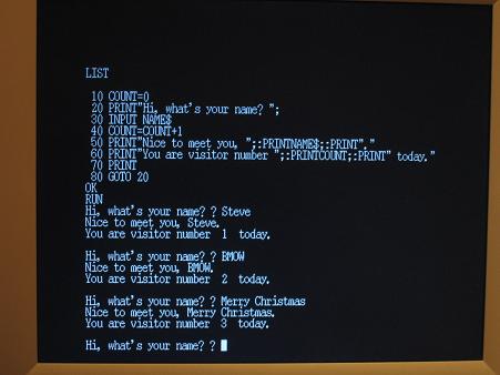
- Boot into a simple integer BASIC program, capable of interactively editing and running its own programs.
- Support multiple programs executing simultaneously, via a pre-emptive multitasking OS.
- Provide keyboard input, VGA video and sound output.
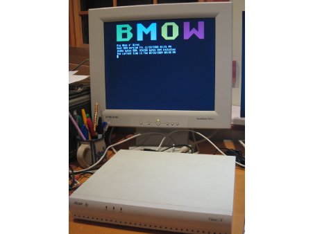
Initial design began in November 2007 with a high-level sketch of the CPU internal design. A simplified Verilog hardware simulation proved the key design details. Construction began in earnest in February 2008, using a large wire-wrap board to interconnect the 50 or so chips needed. In April, a half-finished BMOW 1 booted up for the first time, computing fibonacci(12) = 144 using a simple ROM-based program. One by one the original system goals and stretch goals were met, including VGA video, three voice audio, BASIC, and a bootloader for communication with an attached PC. BMOW 1 eventually gained the ability to run complex programs written in assembly or compiled from C. The main construction phase ended in February 2009, with the completion of a customized case to house everything. As of March 2009, Big Mess o’ Wires 1 is fully functional, but will probably never be “finished”.
Architecture
BMOW 1 borrows liberally from other homebrew designs, as well as the MAYBE design presented in the book Computation Structures by Stephen Ward and Robert Halstead. Data busses are 8 bits wide, and the address bus is 24 bits. Four 8-bit registers are used for general data, and three 24-bit registers store the program counter, stack pointer, and a scratch/working address pointer. Registers and the arithmetic and logic unit are interconnected by one data bus, while RAM, ROM, and memory-mapped hardware devices use a second data bus. The ALU also has dedicated left and right data input busses.
Machine language instructions are implemented as a series of micro-instructions, stored in three parallel ROMs to create a 24-bit microcode word. One micro-instruction is executed each clock cycle, and the micro-instruction bits are used directly as enable and select inputs to control all the chips in the machine. Up to 16 micro-instructions may be needed to implement a single machine language instruction.
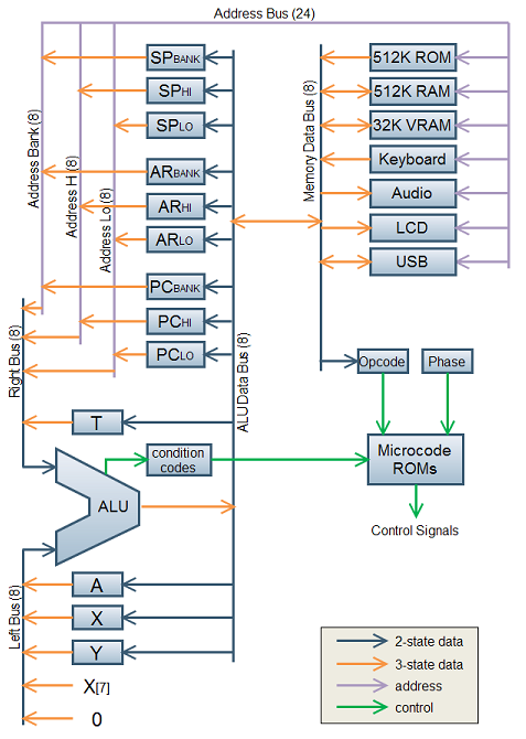
Note: Some additional devices are not shown here, including the VGA display circuitry and real-time clock.
24-bit addresses allow for up to 16MB of memory, but only a little more than 1MB of combined RAM and ROM is installed. The most-significant byte of the address is called the bank byte, and is normally invisible to programs. The standard instruction set presents a 16-bit interface to programs, with most instructions implicitly referencing the current bank. Cross-bank references are possible, but awkward (think x86 segment registers).
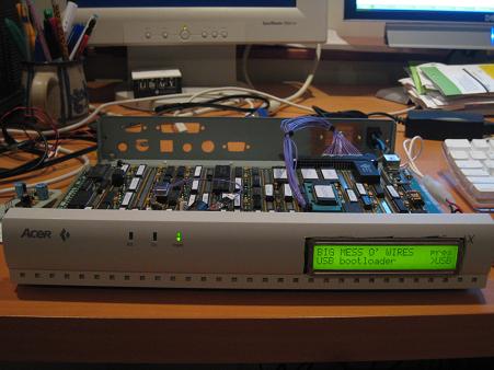
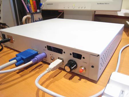
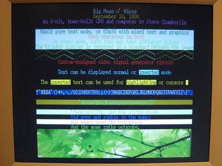
A 512K ROM contains a bootloader/menu program. A USB-to-TTL interface based on an FTDI chip provides an easy way to move data to and from a connected PC. A standard PC keyboard with PS/2 connector is used for keyboard input, and a 24×2 character text LCD serves as a debug output display. Custom video circuitry drives a standard VGA monitor, with a maximum resolution of 512 x 480. A three-voice programmable sound generator provides music and sounds.
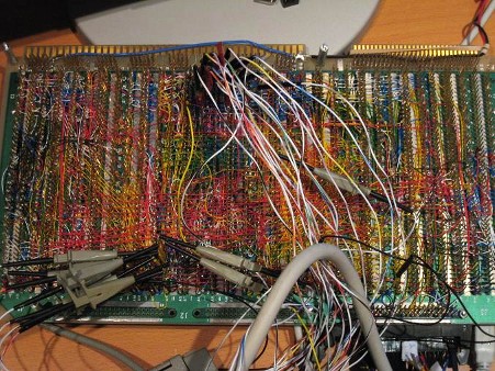
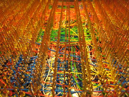
BMOW 1 is built on an Augat wire-wrap board pre-populated with thousands of wire-wrap pins. The chips are pushed into the board without soldering, and can be easily removed, similar to a prototyping breadboard. Unlike a breadboard, the pins are individually connected on the underside of the board according to the needs of the circuit design. A wire-wrap tool is used to wrap stripped wire ends tightly around each pin. Wires can be removed fairly easily in case of a mistake. BMOW 1 contains about 2500 such wire wraps.
Specs
- Current clock speed is 2MHz. It could theoretically go to about 3MHz (untested).
- 512 KBytes of RAM, 512 KBytes of ROM.
- Power draw is 10 Watts, 2.0A at 5V.
- VGA video output is 512×480 with two colors, or 128×240 with 256 colors.
- Audio and music is provided by a three-voice programmable sound generator.
- Keyboard input is a standard PC keyboard with PS/2 connector.
- Debug display is a 24×2 character text LCD.
- There are roughly 1250 wires connecting the components, so 2500 individual hand-turned wire wraps.
Please send me your thoughts and questions!

BMOW 1 Photo Gallery

Faire Preparations
 Four more days until the Maker Faire, and preparations have reached a fever pitch. I was interviewed by a Wired reporter on Friday, and a photographer is coming tomorrow to get pictures of me in my “workshop”, which should be good for a laugh. It’s all for an article that will appear on wired.com Wednesday or Thursday.
Friday is setup day, and I’ve arranged to take the day off from work. It’s not that I really need much setup, but I want to be there while everyone else is setting up, and scope out the exhibits. There are also a couple of Maker-to-Maker events on Friday before the faire opens to the public Saturday morning, including a Maker dinner on Friday night that I’m pretty excited about.
Big Mess o’ Wires will be in the main Expo Hall, booth 296. It’s on the other side of the floor from the Sparkfun booth, in a cluster of about a dozen other small booths. It looks like a pretty good location, near one of the doors so it’ll get some traffic, and not next to the bathroom or behind the stage or someplace similarly odd, so I’m optimistic. I’ve also recruited a couple of friends to be the BMOW crew for the weekend, so there will be someone on hand if I need to leave the booth for a while, or to help handle the teeming crowds that will no doubt be packing the BMOW booth. *cough*
Meanwhile, preparations on the home front are nearly complete. BMOW is fitted with its new transparent laser-etched cover, and tested with its demo attract loop. I’ve got photos, stickers, T-shirts, a “making of” book, and a technical manual with all the schematics and other documentation. I’ve even got a dummy wire-wrap board for people to check out, or try their hand at doing some wraps themselves.
I’ve created a BMOW Powerpoint presentation to answer the questions of “what is this, and why should I care”, which will be looping continuously on another computer in the booth. I welcome feedback on anything that has too much or too little detail, or other general suggestions for improvements.
I hope to meet some of you in person this weekend at the faire!
Edit: The WIRED article about BMOW is up. Thanks Priya!
Be the first to comment!More Uzebox
Finally, I got the Uzebox to work! I’m not quite sure what made the difference, though.
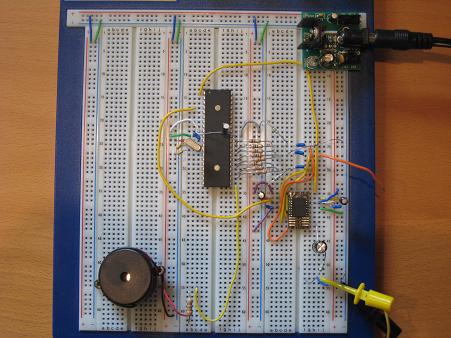
First, I tore apart my earlier breadboard setup, and rebuilt the circuit from scratch, as neatly as I possibly could. Then I scrapped my grayscale DAC, and dropped the AD725 RGB to NTSC chip into the circuit (which had arrived in the mail since my previous attempts). Soldering the AD725 was my first experience at SMD soldering, and it was a little challenging, but not too bad. I managed to get 15 of the 16 pins soldered successfully on the first attempt, but the last pin just wouldn’t bond to the pad. I must have made 20 attempts to solder it, and was about to give up and solder a jumper wire to the pin, when I finally got it.
I connected the circuit to my finicky Dell monitor, turned it on, and voila! It worked!
The image quality is OK, but seems a bit blurry, and there’s noticeable color blooming. The interior of a red letter R is dark red instead of black, for instance. The photos here actually make it look cleaner than it really is. It’s certainly very playable, though, and maybe I’ve just forgotten what composite video quality looks like.
The rewired circuit on the breadboard:
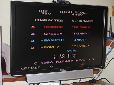
Pac-Man title screen on the Dell monitor:
Pac-Man maze on the Dell monitor:
