

Lower International Shipping Costs!

Good news for BMOW fans from outside the United States: international shipping costs for most orders should now be substantially lower than before. I wrote about the pain of international shipping costs a few weeks ago, and ever since then it’s been on my mind. Since about half of all BMOW customers are outside the US, I want to do everything I can to make their shopping easy and inexpensive, and I’m glad I’ve finally been able to address the shipping issue.
So how did I do it? The weight-based shipping rates haven’t changed, and those are set by the US Postal Service. Since I can’t lower the postage cost for a given weight, I instead focused on reducing the weight for a given item by using ultra-light packaging material whenever possible. Instead of shipping international orders in bulky and heavy cardboard boxes, many orders will now ship in padded mailing envelopes with a triple-layer of bubble wrap inside to protect the contents. I’ve tested this to several different destination countries, and it’s proven to protect the contents just as well as a box. Lower weight means lower shipping costs, so everybody wins.
International shipping costs for typical orders will be 40% cheaper thanks to this change. Most orders will now fall under the critical 0.5 pound threshold where higher postage rates take effect. Overseas customers will see typical shipping costs reduced from $24.25 to $15.25, and Canadian customers will see a reduction from $17.00 to $11.00. Hooray!
Read 2 comments and join the conversationFC8 – Faster 68K Decompression

Data compression is fun! I’ve written a new compression scheme that’s designed to be as fast as possible to decompress on a 68K CPU, while still maintaining a decent compression density. I’m calling it FC8, and you can get the generic C implementation and optimized 68K decompressor from the project’s Github repository. I’ve probably reinvented the wheel with this, and in a non-optimal way too, but once I started I found that I couldn’t stop. My intended platform for FC8 is 68020 and 68030-based vintage Macintosh computers, but it should be easily portable to other classic computers, microcontrollers, and similar minimal systems.
The main loop of the 68K decompressor is exactly 256 bytes, so it fits entirely within the instruction cache of the 68020/030. Decompression speed on a 68030 is about 25% as fast as an optimized memcpy of uncompressed data, which is essentially an unrolled loop of 4-byte move.l instructions with no computation involved. Compared to that, I think 25% is pretty good, but I can always hope for more. 🙂
In the previous post, I described how I was using compression to squeeze a larger rom-disk image into a custom replacement Macintosh ROM that I’m designing. I began with a compression algorithm called LZG, written by Marcus Geelnard. It worked well, but the 68K decompression seemed disappointingly slow. I tried to contact the author to discuss it, but couldn’t find any email address or other contact info, so I eventually drifted towards creating my own compression method loosely based on LZG. This became FC8. On a 68030 CPU, FC8 compresses data equally as tightly as LZG and decompresses 1.5x to 2x faster. FC8 retains much of the compression acceleration code from LZG, as well as the idea of quantizing lengths, but the encoding and decompressor are new.
The algorithm is based on the classic LZ77 compression scheme, with a 128K sliding history window and with duplicated data replaced by (distance,length) backref markers pointing to previous instances of the same data. No extra RAM is required during decompression, aside from the input and output buffers. The compressed data is a series of tokens in this format:
- LIT = 00aaaaaa = next aaaaaa+1 bytes are literals
- BR0 = 01baaaaa = backref to offset aaaaa, length b+3
- EOF = 01×00000 = end of file
- BR1 = 10bbbaaa’aaaaaaaa = backref to offset aaa’aaaaaaaa, length bbb+3
- BR2 = 11bbbbba’aaaaaaaa’aaaaaaaa = backref to offset a’aaaaaaaa’aaaaaaaa, length lookup_table[bbbbb]
The encoding may look slightly strange, such as only a single bit for the backref length in BR0, but this produced the best results in my testing with sample data. The length lookup table enables encoding of backrefs up to 256 bytes in length using only 5 bits, though some longer lengths can’t be encoded directly. These are encoded as two successive backrefs, each with a smaller length.
The biggest conceptual changes vs LZG were the introductions of the LIT and EOF tokens. EOF eliminates the need to check the input pointer after decoding each token to determine if decompression is complete, and speeds things up slightly. LIT enables a whole block of literals to be quickly copied to the output buffer, instead of checking each one to see if it’s a backref token. This speeds things up substantially, but also swells the size of the data. In the worst case, a single literal would encode as 1 byte in LZG but 2 bytes in FC8, making it twice as expensive! All the other changes were needed to cancel out the compression bloat introduced by the LIT token, with the end result that FC8 compresses equally as compactly as LZG. Both compressed my sample data to about 63% of original size.
The 68K decompressor code can be viewed here.
Decompression on the Fly
Several people mentioned the possibility of on-the-fly decompression, since the intended use is a compressed disk image. That’s something I plan to explore, but it’s not as simple as it might seem at first. Disk sectors are 512 bytes, but there’s no way to decompress a specific 512 byte range from the compressed data, since the whole compression scheme depends on having 128K of prior data to draw on for backref matches. You could compress the entire disk image as a series of separate 512 byte blocks, but then the compression density would go to hell. A better solution would compress the entire disk image as a series of larger blocks, maybe 128K or a little smaller, and then design a caching scheme to keep track of whether the block containing a particular sector were already decompressed and available. This would still have a negative impact on the compression density, and it would make disk I/O slower, but would probably still be OK.
Ultimately I think the two decompression approaches each have strengths and weaknesses, so the best choice depends on the requirements.
Boot-Time Decompression:
Pros: Best compression density, fastest I/O speeds once the disk image is decompressed
Cons: 5-10 second wait for decompression at boot time, requires enough RAM to hold the entire disk image
On-the-Fly Decompression:
Pros: No wait at boot time, required amount of RAM is configurable (size of the decompressed block cache)
Cons: Worse compression density, slower I/O speeds, more complex implementation
Hardware Tests
I discovered that a Macintosh IIci in 8-bit color mode decompresses about 20% slower than in 1-bit color mode. But a IIsi decompresses at the same speed regardless of the color settings. Both machines are using the built-in graphics hardware, which steals some memory cycles from the CPU in order to refresh the display. I’m not sure why only the IIci showed a dependence on the color depth. Both machines should be faster when using a discrete graphics card, though I didn’t test this.
The original LZG compression showed a much bigger speed difference between the IIci and IIsi, closer to a 50% difference, which I assumed was due to the 32K cache card in the IIci as well as its faster CPU. It’s not clear why the discrepancy is smaller with FC8, or whether it means the IIci has gotten worse or the IIsi has gotten better, relatively speaking. Compared to the same machine with the LZG compression, FC8 is 1.57x faster on the IIci and 1.99x faster on the IIsi. Based on tests under emulation with MESS, I was expecting a 1.78x speedup.
Tradeoffs
While working on this, I discovered many places where compression compactness could be traded for decompression speed. My first attempt at FC8 had a minimum match size of 2 bytes instead of 3, which compressed about 0.7% smaller but was 13% slower to decompress due to the larger number of backrefs. At the other extreme, the introduction of a LIT token without any other changes resulted in the fastest decompression speed of all, about 7% faster than FC8, but the compressed files were about 6% larger, and I decided the tradeoff wasn’t worth it.
I explored many other ideas to improve the compression density, but everything I thought of proved to have only a tiny benefit at best, not enough to justify the impact on decompression speed. An algorithm based on something other than LZ77 would likely have compressed substantially more densely, or say a combination of LZ77 and Huffman coding. But decompression of LZ77-based methods are far easier and faster to implement.
Compression Heuristics
It eventually became obvious to me that defining the token format doesn’t tell you much about how to best encode the data in that format. A greedy algorithm seemed to work fairly well, so that’s what I used. At each point in the uncompressed data, the compressor substitutes the best match it can make (if any) between that data and previous data in the history window.
However, there are some examples where choosing a non-optimal match would allow for an even better match later, resulting in better overall compression. This can happen due to quirks in the quantizing of match lengths, or with long runs of repeated bytes which are only partially matched in the previous data. It’s a bit like sacrificing your queen in chess, and sometimes you need to accept a short-term penalty in order to realize a long-term benefit. Better compression heuristics that took this into account could probably squeeze another 1% out of the data, without changing the compression format or the decompressor at all.
Read 11 comments and join the conversationOptimizing Assembly (Fast 68K Decompression)

Are you a 68K assembly language guru, or just good at optimizing code? I’m working on a project that’s a replacement ROM for old 68K-based Macintosh computers, part of which involves decompressing a ~5MB disk image from ROM into RAM to boot the machine. This needs to happen fast, to avoid a lengthy wait whenever the computer boots up. I selected liblzg specifically for its simplicity and speed of decompression, even though it doesn’t compress as well as some alternatives. And the whole thing works! But I want it to be faster.
The compressor is a regular Windows/Mac/Linux program, and the decompressor is a hand-written 680000 assembly routine from the lzg authors. It works well, but decompression on a Mac IIsi or IIci only runs about 600K/sec of decompressed data, so it takes around 5-20 seconds to decompress the whole rom disk depending on its size and the Mac’s CPU speed.
The meat of the 68000 decompression routine isn’t too long. It’s a fairly simple Lempel-Ziv algorithm that encodes repeated data as (distance,length) references to the first appearance of the data. There’s a brief summary of lzg’s specific algorithm here. Anyone see any obvious ways to substantially optimize this code? It was written for a vanilla 68000, but for this Mac ROM it’ll always be running on a 68020 or ‘030. Maybe there are some ‘030-specific instructions that could be used to help speed it up? Or some kind of cache prefetch? There’s also some bounds-checking code that could be removed, though the liblzg web site says this provides only a ~12% improvement.
The meat-of-the-meat where data gets copied from source to dest is a two-instruction dbf loop:
_loop1:	move.b	(a4)+,(a1)+
	dbf	d6,_loop1
If any ‘030-specific tricks could improve that, it would help the most. One improvement would be to copy 4 bytes at a time with move.l instead of move.b. But the additional instructions needed to handle 4-byte alignment and 1-3 extra bytes might outweigh the savings for smaller blocks being copied. I think the average block size is around 10 bytes, though some are up to 127 bytes.
The loop might also be unrolled, for certain pre-defined block sizes.
Here’s the entirety of the decompressor’s main loop:
_LZG_LENGTH_DECODE_LUT:
	dc.b	1,2,3,4,5,6,7,8,9,10,11,12,13,14,15,16
	dc.b	17,18,19,20,21,22,23,24,25,26,27,28,34,47,71,127

_lzg_decompress:
	// a0 = src
	// a1 = dst
	// a2 = inEnd = in + inSize
	// a3 = outEnd = out + decodedSize
	// a6 = out
	move.b	(a0)+,d1			// d1 = marker1
	move.b	(a0)+,d2			// d2 = marker2
	move.b	(a0)+,d3			// d3 = marker3
	move.b	(a0)+,d4			// d4 = marker4

	lea		_LZG_LENGTH_DECODE_LUT(pc),a5	// a5 = _LZG_LENGTH_DECODE_LUT

	// Main decompression loop
	move.l	#2056,d0			// Keep the constant 2056 in d0 (for marker1)
	cmp.l	a2,a0
_mainloop:
	bcc.s	_fail				// Note: cmp.l a2,a0 must be performed prior to this!
	move.b	(a0)+,d7			// d7 = symbol

	cmp.b	d1,d7				// marker1?
	beq.s	_marker1
	cmp.b	d2,d7				// marker2?
	beq.s	_marker2
	cmp.b	d3,d7				// marker3?
	beq.s	_marker3
	cmp.b	d4,d7				// marker4?
	beq.s	_marker4

_literal:
	cmp.l	a3,a1
	bcc.s	_fail
	move.b	d7,(a1)+
	cmp.l	a2,a0
	bcs.s	_mainloop

	// We're done
_done:
	// irrelevant code removed
	bra _exit

	// marker4 - "Near copy (incl. RLE)"
_marker4:
	cmp.l	a2,a0
	bcc.s	_fail
	moveq	#0,d5
	move.b	(a0)+,d5
	beq.s	_literal			// Single occurance of the marker symbol (rare)
	move.l	d5,d6
	and.b	#0x1f,d6
	move.b	(a5,d6.w),d6		// length-1 = _LZG_LENGTH_DECODE_LUT[b & 0x1f]
	lsr.b	#5,d5
	addq.w	#1,d5				// offset = (b >> 5) + 1
	bra.s	_copy

	// marker3 - "Short copy"
_marker3:
	cmp.l	a2,a0
	bcc.s	_fail
	moveq	#0,d5
	move.b	(a0)+,d5
	beq.s	_literal			// Single occurance of the marker symbol (rare)
	move.l	d5,d6
	lsr.b	#6,d6
	addq.w	#2,d6				// length-1 = (b >> 6) + 2
	and.b	#0x3f,d5
	addq.w	#8,d5				// offset = (b & 0x3f) + 8
	bra.s	_copy

	// marker2 - "Medium copy"
_marker2:
	cmp.l	a2,a0
	bcc.s	_fail
	moveq	#0,d5
	move.b	(a0)+,d5
	beq.s	_literal			// Single occurance of the marker symbol (rare)
	cmp.l	a2,a0
	bcc.s	_fail
	move.l	d5,d6
	and.b	#0x1f,d6
	move.b	(a5,d6.w),d6		// length-1 = _LZG_LENGTH_DECODE_LUT[b & 0x1f]
	lsl.w	#3,d5
	move.b	(a0)+,d5
	addq.w	#8,d5				// offset = (((b & 0xe0) << 3) | b2) + 8
	bra.s	_copy

	// marker1 - "Distant copy"
_marker1:
	cmp.l	a2,a0
	bcc.s	_fail
	moveq	#0,d5
	move.b	(a0)+,d5
	beq.s	_literal			// Single occurance of the marker symbol (rare)
	lea		1(a0),a4
	cmp.l	a2,a4
	bcc.s	_fail
	move.l	d5,d6
	and.b	#0x1f,d6
	move.b	(a5,d6.w),d6		// length-1 = _LZG_LENGTH_DECODE_LUT[b & 0x1f]
	lsr.w	#5,d5
	swap	d5
	move.b	(a0)+,d5
	lsl.w	#8,d5
	move.b	(a0)+,d5
	add.l	d0,d5				// offset = (((b & 0xe0) << 11) | (b2 << 8) | (*src++)) + 2056

	// Copy corresponding data from history window
	// d5 = offset
	// d6 = length-1
_copy:
	lea		(a1,d6.l),a4
	cmp.l	a3,a4
	bcc	_fail

	move.l	a1,a4
	sub.l	d5,a4

	cmp.l	a6,a4
	bcs	_fail

_loop1:	move.b	(a4)+,(a1)+
	dbf	d6,_loop1

	cmp.l	a2,a0
	bcs	_mainloop
	bra	_done
Another thing to note is that about half of all the data is literals rather than (distance,length) markers, and goes to the _literal branch above. That involves an awful lot of instructions to copy a single byte. A faster method of determining whether a byte is a marker or a literal would help - I plan to try a 256-entry lookup table instead of the four compare and branch instructions.
My final idea would involve changing the lzg algorithm itself, and making the compression slightly worse. For longish sequences of literals, the decompressor just copies bytes from input to output, but it goes through the whole _literal loop for each byte. I'm thinking of introducing a 5th marker byte that means "copy the next N bytes directly to output", for some hand-tuned value of N. Then those N bytes could be copied using a much higher performance loop.
Read 35 comments and join the conversationCapacitor Replacement in a Vintage Power Supply
Capacitors don’t last forever – an unfortunate fact of life for those who collect vintage electronics. The common electrolytic capacitor is one of the most problematic. It’s the type that looks like a little metal can, and after a couple of decades electrolytics tend to start leaking corrosive capacitor goo onto the PCB. You may recognize the strange smell of fish as an early warning sign. Eventually the goo will destroy traces on the PCB, or the changing electrical properties of the capacitor will cause the circuit to stop working. If you want to preserve your vintage equipment, that’s when it’s time for a “recap”.
I have an old Macintosh IIsi computer that dates from around 1991. A few years ago it started acting funny and having trouble turning on, so I sent the logic board to Charles Phillips’ MacCaps Repair Service. He did a great job with the capacitor replacement, and the machine was working great again. But then a few months ago it started to develop new problems that pointed to the need for a power supply recap. I could rarely get it to turn on at all, and when it did, I couldn’t get it to turn off again without unplugging it. Simply plugging the computer into wall power without turning it on caused strange clicking noises from the PSU. And oh, that fish smell.
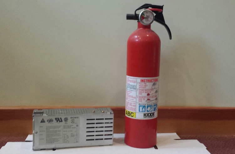
I was going to send the PSU off for a recap. After all, there’s a big warning printed right on the metal cover saying danger, do not open, no user-serviceable parts inside. And while there’s not much danger in a 5 volt logic board, there is a potential for real danger in a power supply drawing 5 amps at 110 volts AC. But then I thought no, I should really get comfortable doing this kind of work myself. I have the tools and the skills, just not the experience or confidence. What’s the worst that could happen? OK, it could blow up and catch fire, but I’ve got a fire extinguisher. 🙂
There are 12 electrolytic capacitors in this power supply, whose types and values are listed here. Two of these are surface mount caps on a daughterboard that’s connected to the main PCB, and the others are all through-hole caps. Because I’m both timid and lazy, I really did not want to replace 12 caps. After reading this discussion thread from someone who did a similar repair, I decided to replace only the three capacitors that seemed most likely to be causing the problem. Two of these were the SMD caps on the daughterboard, which apparently are involved in some kind of PWM control circuit. The third was a 400V cap in the AC section of the power supply. It’s located directly next to some big heat sink thing, and has probably been slowly baking for 25 years.
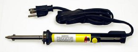
To help with the job, I bought a cheapo vacuum desoldering iron. This makes desoldering of through-hole components easy. Just put the iron over the pin, hold for a second, then press the button to release the plunger and mostly all the solder is sucked up. I used this to desolder the daughterboard too. I had to revisit a few pins to get them totally clean, but overall the process was simple. I don’t do enough desoldering to justify the cost of a fancier desoldering gun with a continuous suction vacuum pump, so this seemed like a good tool for occasional use.
I removed the two SMD capacitors on the daughterboard with a hot air tool. I’m not sure how you would do that without such a tool – just rip them off with pliers? The hot air worked fine, except when I used tweezers to slide off the caps after the solder had melted, I accidentally pushed one of them right through a bunch of other little SMD components, whose solder had also melted, and ended up with a jumbled heap of little components half soldered together in a corner of the board. Ack!!
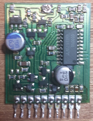
Here’s the daughterboard, before I wrecked it. The four components at bottom right were all pushed into a pile in the corner. A couple of them actually fell off the board, as did one of the pins. But with some patience I was able to separate them all and get things cleaned up, and I think I even put everything back where it was originally. 🙂 After removing the old caps, I cleaned up the board with isopropyl alcohol and a toothbrush to remove the capacitor goo.
The last step was soldering in new capacitors, and putting it all back together. Compared to everything else, that was a breeze.
When the time came for testing, I didn’t take any chances. I brought the whole machine outside, with a fire extinguisher in hand, ready for anything! I plugged it in, pressed the power switch, and… WOOHOO! It booted right up, and everything now looks a-ok. I can boot from the rear power switch or the keyboard power button, and the soft power-off function works again too. I feel like Superman!
This was my first time recapping anything, and I won’t be so timid about recapping next time the need arises. The whole process took about three hours, including lots of futzing around during disassembly and reassembly. If I hadn’t blundered by knocking off a bunch of unrelated SMD parts, I probably could have done the whole job in about an hour.
Read 18 comments and join the conversationIdentify the Mystery Components
I’m planning to do a partial capacitor replacement on the power supply of my old Macintosh IIsi computer. After 25+ years, these capacitors aren’t in the best condition, and the PSU doesn’t work correctly anymore. When plugged in, it makes odd clicking sounds for a few seconds, then does nothing, and the computer won’t boot. Occasionally if I plug it in, unplug it, plug it in again, and say some magic words, I can get the computer to boot. But it’s clearly on its last legs, and the research I’ve done says replacing a few key capacitors will likely fix it.
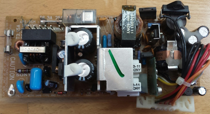
After dismantling the PSU and removing its circuit board, I was surprised by some of the components I found inside. I’ve never looked inside a power supply before, so this was all new to me.
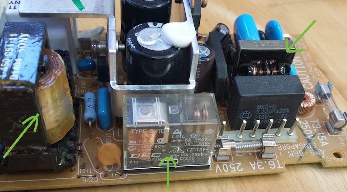
In the center is a relay. I’m not sure why there’s a relay inside a PSU, but there it is. At right is probably a transformer? It has some exposed wire windings, and is located close to where 110V AC comes in, so I assume that’s it. At left is… something. A capacitor? It looks like a rolled up length of plasticized paper, coated in oil.
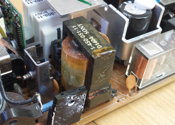
Here’s a closer look at the mystery capacitor thing.
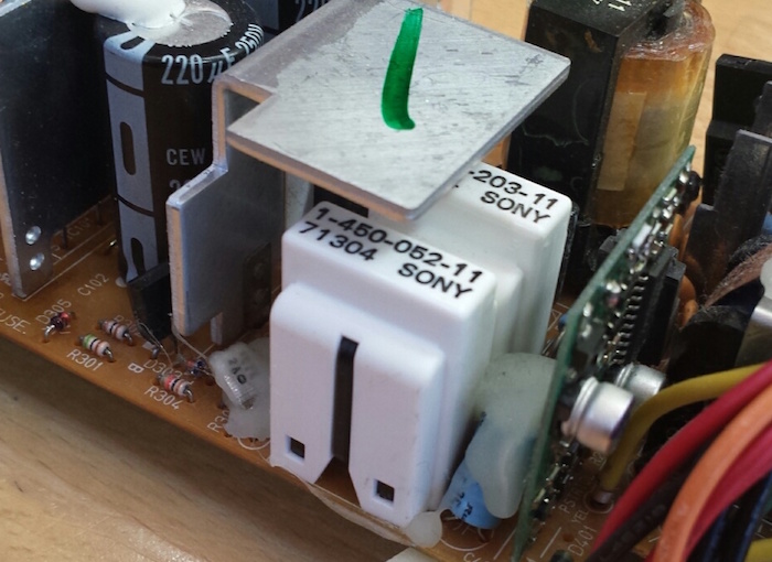
On the other side of the PSU circuit board are two white plastic towers. They look like they might be removable covers. What are these, and what mysteries do they hide?
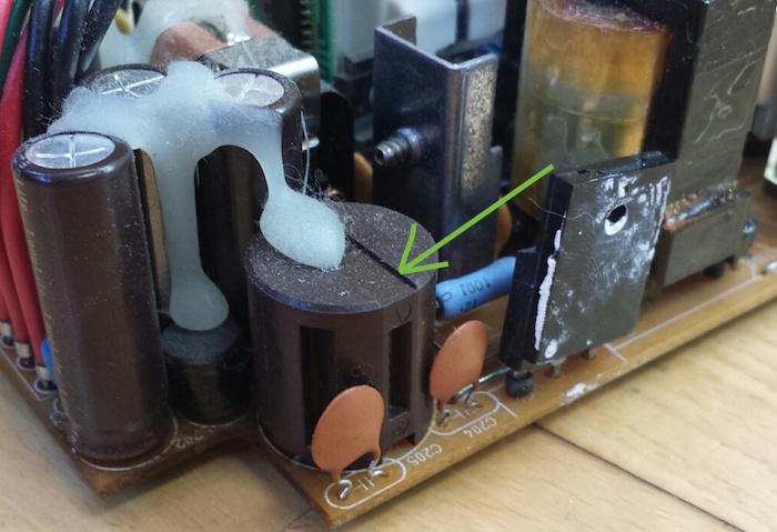

At the end of the board opposite the AC power connection, there are two cylindrical components that look sort of like capacitors, but aren’t. They have vertical grooves cut into them at regular intervals around their circumference. The smaller of the two has 4R7 stamped into its plastic case, and the larger one is marked 830. Could these be some kind of high-power resistor, maybe?
Read 14 comments and join the conversationMore USB-to-ADB Planning
This must be a record for the number of times I’ve posted about a project, without actually building the project, or even a half-way working prototype. I’m still fleshing out my ideas for a USB-to-ADB keyboard/mouse adapter for vintage Macintosh and Apple IIgs computers. In my last update, I described how USB interrupts would interfere with the software timing loops in my bit-banged ADB implementation, and sketched out a few possible solutions to the problem.
After more thought and research, I’ve decided to try the approach that my last post called “timer hacking”. It isn’t really a hack, but rather a better (but more complex) implementation of ADB for the microcontroller. It means removing all the blocking code and software delay loops from my initial ADB implementation, and replacing them with interrupts driven from timers and pin state change events. The ADB-related interrupts will be given higher priority than USB interrupts, and can even interrupt the USB interrupt handler. Because this new ADB code will be interrupt driven, using hardware timers, simultaneous USB activity shouldn’t cause any timing errors. I’m reasonably confident this should all work, but it’ll take time to implement.
I discovered that the PIC32MX I’m using has an input capture feature with a 4-deep FIFO. That will be much nicer than using a basic pin state change interrupt, because input capture records a timer value at the instant a pin changes state, instead of sometime later when the interrupt handler runs and executes code to query the current timer value. So timing measurements when reading ADB will be more accurate. The FIFO means the ADB interrupt handler will only need to be invoked after every 4 rising/falling edges on the ADB signal, instead of for every edge, which will help make things a little more efficient. For writing ADB, I’ll look at using the microcontroller’s built-in PWM hardware, changing the pulse width for each ADB bit, which should be slightly more efficient than using a simple hardware timer to toggle the ADB pin.
Taking a Break
Unfortunately, I can’t actually pursue this plan yet, with the PIC32MX USB Starter Kit II that I’ve been using. This kit has virtually none of the PIC’s pins broken out onto headers, essentially no I/O at all except for the USB ports. Earlier I managed to hack in a single external input by soldering a wire to an unused crystal footprint on the board, which was enough for some simple experiments. But that particular pin isn’t connected to the PIC32MX’s input capture peripheral. Some PIC32MX’s have the ability to dynamically remap the pins, but not this particular one. So in short, I can’t use input capture with this hardware.
Even if that weren’t the case, there are other reasons I want access to more I/O pins. It would be a huge help with debugging if I could connect a serial terminal to the PIC’s UART, and log messages with it. While there’s already a built-in debug-print capability that operates over USB, it seems incredibly slow, on the order of 100 characters per second. And I’d also like additional I/O to experiment with some of this device’s other planned features, like a power-on button connected to ADB’s “on” pin. I’d also like to start testing with the actual model of PIC32MX I plan to use in the final device, instead of the high-end PIC32MX795 in the USB Starter Kit. So it’s time for me to order a bunch of discrete parts, or maybe some much simpler PIC32MX prototyping board, and get working on a real prototype.
The trouble comes when I need to program the PIC32MX on this new board or prototype. Many are designed to be programmed via USB, but I can’t do that if the USB interface is already in use as a USB host. The USB Starter Kit II works around that problem by having two separate PICs, each with their own USB interface, but that’s complex and expensive. The other solution is to use a programmer like a PICkit 3 to program the chip via its ICSP pins, so that’s what I’ll do. Except I don’t own a PICkit 3. I ordered a PICkit 3 clone a while ago from Aliexpress, but it probably won’t arrive for several weeks. Until that happens, I’ll be taking a break from this project, aside from possible further sketching out of ideas on paper.
Read 11 comments and join the conversation