

Building an SRAM Substitute
How would you use modern RAM and interface logic to replace 8 MB of vintage SRAM? A cheap and simple solution would make a big difference for many retrocomputing and hobby electronics projects. This question arose from a discussion at 68kmla.org, from a project to design an 8 MB RAM expansion card for the 1989 Macintosh Portable, and it piqued my interest. Modern components are so much cheaper and more capable than their 1980’s equivalents, there must be a way.
As you might remember from long-ago engineering classes, standard computer RAM comes in two basic types: static RAM (SRAM) and dynamic RAM (DRAM). SRAM is very convenient and easy to use. The CPU places an address on the SRAM’s address pins, and some short time later the CPU can read the value stored at that address from the SRAM’s data pins. Once stored, values remain in SRAM for as long as the power is kept on. DRAM usage is more complex. The CPU places half of the address bits on the DRAM’s address pins (the row address), then a short time later it removes these and places the other half of the address bits on the DRAM’s address pins (the column address), and only then can it read the value stored at that address. The stored values are not persistent, but will be lost after a few milliseconds unless they are constantly refreshed.
For retro/hobby projects, SRAM is ideal because there’s no memory controller or refresh logic required. The Mac Portable RAM expansion card also uses SRAM, because that’s what the Portable was designed to use – perhaps to save power that would otherwise be lost to refresh cycles while the computer was asleep.
The problem is that in 2015, SRAM is rarely used anymore. The RAM in your new Windows or OSX machine is all some flavor of DRAM. A search of popular online electronics vendors like Digi-Key, Mouser, and Farnell reveals that few SRAM chips are available for sale today, and the ones that are available are low capacity and expensive. For the Mac Portable 8 MB RAM expansion card, the most likely candidate is this 2 MB Alliance Memory SRAM chip – so four chips would be required. But that chip is $10 each! You’d have $40 in RAM costs before even considering the cost of the other components, the PCB, and assembly. $40 for 8 MB of RAM seems crazy, when you can buy 8 GB of modern RAM for about the same price.
Building a Frankenstein RAM
Can some flavor of modern DRAM be used, along with some interface glue logic, to make an 8 MB RAM card that looks like SRAM to the Mac Portable? In theory, I believe it’s possible, but the details look tricky. The SRAM speed is 55 ns, meaning the CPU must wait 55 ns after presenting the address before it can read the value stored there. The proposed SRAM replacement would need a state machine of some kind that could latch the address, break it into separate row and column addresses, present these to the DRAM, and then grab the stored value and provide it to the CPU, and then do a DRAM refresh cycle, all in less than 55 ns. That’s something like 5 operations, so each one would need to take less than 11 ns, implying a 91 MHz clock rate for the state machine. This state machine would also need to handle any necessary DRAM initialization (CAS latency setting?), and things like burst mode and other DRAM details that I’ve heard of but don’t really know what they are. It could be implemented in a CPLD or FPGA. It would likely require a large number of pins, perhaps 60 or more, for the address and data busses on both sides. That probably rules out most CPLDs, and requires a higher pin count FPGA.
Here’s one candidate chip: an 8 MB Alliance Memory SDRAM that’s just $1.53. The price is certainly right. It looks like it would be fast enough, given my quick peek at the data sheet. But the complexity of building that FPGA memory controller interface is a bit daunting.
How about using some kind of modern synchronous SRAM, instead of DRAM? I’ve never really looked at synchronous SRAM, though I assume from its name it’s like standard SRAM with the addition of a clock for the control signals. But a quick glance at Digi-Key shows that it’s no cheaper than old-school SRAM.
What about using Flash RAM? That’s probably no good – it’s not designed to be constantly modified like a general purpose RAM, and would likely fail after some tens or hundreds of thousands of update cycles. And I’m not certain it would be fast enough, either. Flash is normally a page-centric memory, so in order to modify one memory location, an entire page must be erased and re-written. But it sure is cheap!
Maybe a fast microcontroller could be used instead of an FPGA to implement the memory controller interface. Some of the newer ARM microcontrollers have a built-in DRAM controller, and can run at 100s of MHz. Would it be crazy to consider writing a 10 line program that sits in a tight loop, watching the CPU address and data bus on one set of pins, and fetching/storing data to DRAM on another set of pins?
Other bright ideas?
Read 17 comments and join the conversationApple II Copy Protection
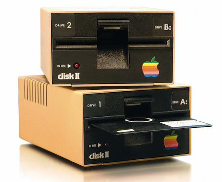
Growing up during the heyday of Apple II computers, I learned about something mysterious called copy-protection. This meant floppy disks could be used to run software, but the software couldn’t be copied to other floppy disks. As a 10-year-old nerd, this left me confused. Running a game or other piece of software required reading the data from the disk. Copying the disk required reading that same data, then writing it back to another disk. How could it be possible for a floppy to be readable when running a program, but not readable when copying the program? It didn’t seem to make sense.
Years later I learned more about copy-protection, and my experiments with Floppy Emu have also provided insights into floppy-specific copy protection methods. It’s fascinating stuff, so let’s look at it! We’ll begin by examining how Apple II floppy disk access works in the normal case, then we’ll see some of the abnormal tricks that were used to implement copy protection. We’ll also look at how floppy access on the original Macintosh differed from the Apple II, and how this affected copy protection.
Floppy Fundamentals and Limitations
A floppy disk is a wheel-shaped disc of magnetic media with a hole in the center. The data is stored in a series of concentric circles, called tracks. Unlike the single spiral groove on a phonograph record, each track on a floppy disk loops back onto itself, and does not intersect or overlap the other tracks. The disk spins continuously with a constant speed and direction, while a stepper motor moves the read/write head inward and outward as needed. To access a specific piece of data, the head must step in/out until it’s over the correct track. To find the desired information, the computer then begins reading data from the track, starting with whatever portion of the track happened to be passing under the head at that moment. It keeps reading until it recognizes a marker for the desired information, then it reads the information itself immediately afterward. The access time is the sum of the time needed to position the head over the proper track plus the time needed to wait until the desired data passes under the head (on average, half a rotation of the disk).

On an Apple II floppy disk, a track is just a circular buffer of about 50,000 bits, with nothing to mark its beginning or end. Even the boundary between one byte and the next is unknown, so framing the bitstream into bytes correctly requires additional work. The disk controller must rely on the first fundamental rule of Apple floppy disks: the most significant bit of a disk byte must always be 1. If at any time the disk controller reads a byte whose MSB is not 1, then the byte framing must be wrong. Adjust the framing by one bit, and try again.
The disk controller must also honor the second fundamental rule of Apple floppy disks: a disk byte may contain no more than two consecutive zero bits. While the first rule is an arbitrary choice to make framing easier, the second rule is a physical limitation imposed by the way data is encoded magnetically. A 1 bit is stored as a reversal of the magnetic polarity on a region of the disk, while a 0 bit is stored as no reversal of magnetic polarity in that region. With too many consecutive zero bits, you’ll get too large of an area with no magnetic reversals. I’m unsure exactly what problem this leads to – the magnetic field in that region becomes too weak, or the read circuitry loses synchronization maybe – but the end result is that it’s forbidden to have more than two consecutive zeroes.
GCR Encoding
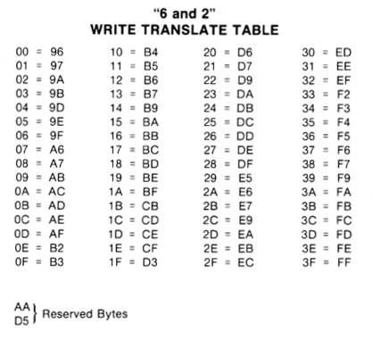
But wait a minute: if the MSB must always be 1, and consecutive zeroes are limited to two, that rules out more than half of all possible byte values. How can you store arbitrary data on a floppy disk, if more than half the possible byte values are forbidden? The answer is that program data and files aren’t stored directly on the floppy disk. Instead, their bytes are encoded in a process that converts logical bytes to disk bytes. On the Apple II, this process is called 6-and-2 Group Code Recording, or just GCR for short. There are 66 possible byte values that satisfy fundamental rules 1 and 2. Setting aside two of these as reserved, this leaves 64 possible disk byte values: enough to encode 6 bits of logical data with a lookup table, because 2 ^ 6 = 64. This means that every three bytes of logical data (24 bits total) will be stored on the floppy disk as four bytes of disk data (one of 64 possible values per byte, so 6 bits per byte, 24 bits total). Thus, data undergoes an expansion of 33% in size when it’s stored on a floppy disk.
Sectors
By itself, the GCR encoding scheme isn’t enough to build a working floppy-based file system. We also need some way to identify where a track begins, and where specific pieces of data lie within a track. On the Apple II, a track is divided into 16 sectors, with 256 bytes of logical data per sector (342 actual disk bytes due to the 33% GCR overhead). The start of each sector is marked with the magic byte sequence D5 AA 96. Because two of those magic bytes are the two reserved values that meet rules 1 and 2 but aren’t used for GCR, this sequence is guaranteed never to occur in the middle of other encoded data. After this sequence lies a few other bytes of header data: the sector number, track number, etc, and then (glossing over some details) the sector data itself. After the sector data, there’s a checksum and another magic sequence to mark the end of the sector.
It’s important to realize that sectors are just arrangements of data in a track. There’s no physical boundary that separates them, and nothing special about them except that they’re regions of data marked with certain magic bytes. Normally the last byte of a sector is not followed by the first byte of the next sector, but instead, there’s a series of so-called self-sync bytes between them. The sync bytes don’t contain any information, but they’re organized in a way that takes advantage of fundamental rule #1: the MSB of a disk byte must always be 1. No matter where the disk controller begins reading and framing bytes in the middle of a series of sync bytes, it will always end up with the correct byte framing after reading at most 5 sync bytes. So a standard floppy disk will always have at least 5 sync bytes between the bytes of two consecutive sectors.
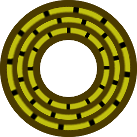
If you search the web for illustrations of a floppy disk’s tracks and sectors, you’ll find lots of diagrams like this:
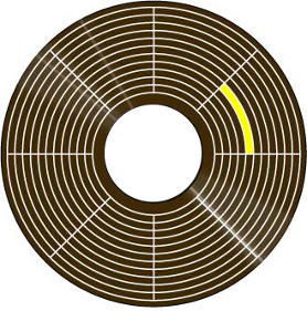
That diagram is misleading in several respects. On a real floppy disk, the sectors in each track aren’t aligned with those in the neighboring tracks, but instead each track is staggered from the next by some random amount. Sectors in the same track aren’t immediately adjacent to each other either – there’s actually a small gap between one sector and the next. Nor are tracks truly adjacent to each other. A real floppy has unused space between one track and the next outer and inner tracks. Here’s a better diagram of a hypothetical three-track floppy disk, showing the stagger offset between sectors in adjacent tracks, the inter-sector gap, and the space between tracks:
Booting from Floppy
When you insert a floppy disk, and reset the Apple II or type PR#6, a small piece of code is run from the disk controller’s ROM. This code knows how to step the head to track 0, look for D5 AA 96, and examine sector headers to find sector 0. Once it finds it, it loads 256 bytes of data from sector 0 into memory, assumes that this data is executable code, and runs it. What happens after that depends on the software, and the code that was loaded from sector 0. Normally this bootstrap code will load additional code and data from other sectors on the disk, until the whole program is loaded and ready to run.
Copying a Floppy (or not)
A simple disk copy program assumes that the floppy being copied is organized in the standard way: 35 tracks, 16 sectors per track, 256 bytes per sector, with a particular checksum algorithm, and D5 AA 96 marking the start of each sector. It attempts to read the data from each sector into memory, then it writes the same data out to a new floppy disk. If anything goes wrong during reading the sectors from the original disk, the copy process will fail.
The crux of copy-protection is this: the bootstrap code loaded from sector 0 has total control over the floppy disk drive and the way the data in other sectors is encoded. Only sector 0 must be encoded and stored in the normal way, so that the initial ROM routine can load it. Thereafter, the software’s bootstrap code has no obligation to follow the standard conventions for track layout, GCR encoding, sector marker magic sequences, or anything else. In fact, pretty much everything is up for grabs.
When this sector 0 bootstrap code is running with the original floppy disk, it knows how to find and load data from the other sectors, using whatever tricky mechanisms the developers used to tweak the standard organization of a floppy disk. But when a disk copying program is running, it sees sector 0 as just part of the data to be copied, and it attempts to copy all the other sectors using the standard methods too. If the copy-protection is good, this attempt will fail, because a sector checksum somewhere will appear invalid, or a sector can’t be found on the track where it was expected, or some other similar problem. Or in some cases the copying will appear to succeed, but then the copied disk won’t work.
The art of cracking copy-protected software involves examining the code stored in sector 0, and analyzing it to understand how it works. With persistence, this will reveal what tricks were used to obfuscate the data in the other sectors. The cracker can then deobfuscate the data, and create a new non-protected floppy disk using the standard disk methods.
Data Tweaks
The easiest way to defeat a simple disk copy program is to alter the sector data in some way that’s consistent, but different from the standard.
Magic Bytes: Who says D5 AA 96 must mark the start of a sector? A copy protected disk might use D5 D5 96, or some other sequence that works just as well, assuming you’re looking for it. But a simple disk copy program will only be looking for D5 AA 96, so it will never find the start of those sectors. It will appear as if the disk is empty.
Checksums: Each Apple II sector is checksummed using a simple algorithm. (See the book Beneath Apple II DOS if you’re curious.) But there’s nothing magic about that algorithm, and a copy protected disk might use another. To the sector 0 bootstrap code, this would be no problem as long as it knew how to compute the new checksum. But to a disk copy program, it would appear as if every sector had a checksum error, and the disk was corrupted.
Bad Sectors: A bad sector that was never intended to be read might be intentionally placed on the original floppy. The program code would know to ignore this sector and not even try to read it, but a disk copy program would try to copy it, and fail.
Duplicate Sectors: Multiple copies of the same sector might be placed in a track, with each copy offset by 90 or 180 degrees along the track’s circumference. These duplicate sectors would contain different contents. Depending on where the head was located within the track when the computer began looking for the sector, it might read any of the copies. On the original floppy disk, repeated reads of that sector would therefore appear to return different results. But a copy of the original disk would contain only one instance of the sector, and so would always return the same result. The bootstrap code could use this difference in behavior to detect whether the floppy were original or a copy.
Sector Size: How about 512 bytes per sector instead of 256? To a standard disk copy program, it would be unintelligible.
More: Offset the sector numbers by some constant delta, insert a pad byte somewhere, disguise the headers with an XOR trick…
Hidden Data
Normally the bytes between the end of one sector and the start of the next are just self-sync bytes. But what if you stored a magic byte sequence in there, and added a routine to the bootstrap code to verify it’s there? A standard disk copy program will only copy the contents of the sectors, and not the apparently useless sync bytes between the sectors. So the copy will appear to succeed, but the copied disk won’t run correctly because the check for the magic byte sequence will fail.
Encoding Tweaks
GCR uses a standard lookup table to convert six bits of logical data into a disk byte, and also to do the reverse translation. But who says a copy-protected program has to use the standard GCR table? Or for that matter, who says it has to use GCR at all? A clever copy-protection designer could use any method he wanted to encode logical bytes as disk bytes, as long as rules 1 and 2 are still satisfied. But a different encoding method from the standard would be unintelligible to most disk copy programs.
Track Hacks
There are 35 tracks on a standard Apple II floppy disk: 35 concentric circles that store data. But the positions and radii of these circles are arbitrary, and there’s no physical track structure on the disk media. Instead, the media is just one continuous piece of magnetic material. Tracks are packed as close to each other as possible, up to the limit where the magnetic field of one track would interfere with its neighbors if they were any closer. An interesting detail: the stepper motor that moves the drive head has a 4x higher resolution than the distance between tracks. It takes four steps of the head to move from one data track to the next. So on a standard floppy disk, if the head is on track 0, it must go step-step-step-step to reach track 1, then step-step-step-step to reach track 2, etc.
So what happens if you’re at track 1, and the drive goes step-step? Where is the head now? It’s on a region of the floppy disk halfway between where track 1 and track 2 are normally stored, which we’ll call track 1.5. You can’t store any data at track 1.5 without interfering with data in track 1 and track 2, because they’re too close together. But a clever copy-protection author can sacrifice a little bit of disk capacity in order to store hidden data in these intermediate non-integer numbered tracks. For example, there might be data on tracks 1, 2, 3, 4.5, 6, 7, 8 etc. A standard disk copy program would see no data on tracks 4 and 5 where it expected it, and it would overlook track 4.5 entirely. Sneaky! The same technique can also be used to make quarter tracks, like track 3.25.
Half and quarter tracks could also be used to measure position dependencies between data in adjacent tracks. For example, during mastering of the original disk, the drive might write a few sectors to track 1, then step to track 1.25 and immediately write more. As long as the track 1.25 sectors didn’t occupy the same part of the track perimeter as the track 1.0 sectors, there would be no magnetic interference. When running the software, the bootstrap routine could read the sectors from track 1, then step to 1.25 immediately after the last sector, and verify that the next thing on track 1.25 was the expected additional sectors. Even a special disk copying program that could handle quarter tracks would have trouble with this, because the relative positions of sectors in tracks 1.0 and 1.25 would not be preserved in the copied disk.
You Big Cheater!
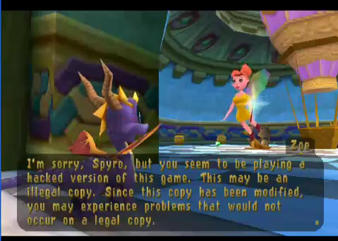
Many Apple II games appeared to copy successfully, but if you ran the copy, you would eventually reach some kind of roadblock complaining “you stole this game!” or otherwise chastising you for making a copy. It’s not hard to see how this might have been done. If we assume the game’s critical initialization code is in sector 1, there might be two copies of sector 1 on the original floppy disk. The real version might have a non-standard sector marker like D5 D5 96, and the decoy version would have the standard sector marker D5 AA 96. A standard disk copy program would copy the decoy version of sector 1 and ignore the real version. If the decoy version contained code to display a “you big cheater” message, it would be displayed when you attempted to run the game from the copied disk.
Macintosh Copy Protection
Although the original Macintosh used a different size and capacity of floppy disk than the Apple II, it still employed a very similar sector structure, with the same GCR encoding method and D5 AA 96 magic sequence to mark the beginning of each sector. In theory, the same types of copy protection tricks used on the Apple II could also have been used on the Macintosh, but in practice relatively few Macintosh programs were copy protected.
Strike 1 against Macintosh floppy-based copy protection: The floppy disk drive on the Macintosh was not capable of quarter or half stepping. This ruled out all the sneaky fractional track methods of copy protection.
Strike 2: The API routines that were used to read and write data from a floppy were considerably more complex on the Mac than the Apple II, and unlike the Apple II, their source code listings were not published. The Mac floppy I/O routines were also asynchronous, designed to run simultaneously with other activity on the mouse, keyboard, or serial port. Embedded in these routines were all the assumptions about D5 AA 96, checksums, sector sizes, and so forth. It would have been possible for a program to bypass all these routines and access the floppy controller (IWM chip) directly, and do the same kind of data or encoding tweaks that were common on the Apple II. But the complexity of the task and the difficulty of multitasking floppy access with mouse and serial port meant that few developers attempted it.
Strike 3: Two years after the introduction of the Macintosh, SCSI hard disks were introduced, and customers began to expect that all software would be installed to their hard disk rather than running directly from the floppy. A program that used floppy-based copy protection would make that impossible, angering customers and hurting sales.

Story Time!
Did you ever work on a copy protection system on the Apple II or another vintage computer system, either as the copy protection developer, or as a cracker? Did I overlook any especially sneaky methods of copy protection, or botch my explanation somewhere? Please leave a note in the comments below, let’s hear your story!
Read 34 comments and join the conversationGS/OS 6.0.2 for Floppy Emu
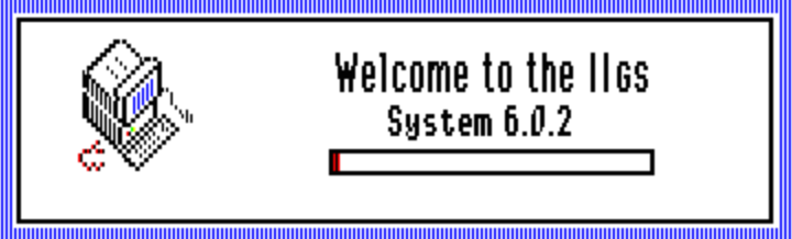
If you follow the Apple II world, then you probably already know that a group of hobbyists recently released GS/OS 6.0.2 – a new version of the Apple IIGS operating system based upon Apple’s last official version from 1993. This new version includes many bug fixes and added features.
To make life easier for Floppy Emu owners, I’ve created this pre-configured GS/OS 6.0.2 hard disk image. It’s a 32 MB ProDOS disk image with GS/OS 6.0.2 already installed and ready to go. If your Floppy Emu has the Apple II firmware installed and is set for Smartport mode, then all you need to do is copy the smart0.po file onto your SD card, and power up your IIGS to begin exploring 6.0.2. Even if you don’t have a Floppy Emu, this disk image should also work with other Apple II hard disk emulators – it’s just a generic ProDOS disk image.
Some software-based Apple IIGS emulators like Sweet16 don’t like ProDOS disk images that are larger than 800K. For those, I’ve also created a pre-configured GS/OS 6.0.2 hard disk image in 2MG format. This 2MG disk image will also work with Floppy Emu, but I/O performance will be worse than with the PO disk image, so the PO version is preferred.
Read 6 comments and join the conversationNibbler PCB Build
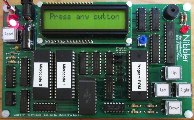
William Buchholz has designed and built a PCB version of my Nibbler 4-bit CPU for his local hackerspace. Nibbler is built entirely from standard 7400 series logic chips – individual counters, registers, buffers, and gates. It’s an educational example of a simple CPU that’s easy to understand and build, but still capable of running games and other interesting programs.
In addition to converting my messy wire-wrap job into an elegant PCB, William also made some component substitutions, including a larger program ROM. Using jumpers connected to the upper 5 address lines, you can select between several different programs without having to reprogram the ROM. More photos of William’s work are here and the schematics and design files are here.
Read 4 comments and join the conversationNew Product: Universal Adapter Extension Cable
January 2016 Update: The current hardware version Floppy Emu Model B has built-in Apple II functionality that’s equivalent to the Universal Adapter described here. The Universal Adapter is therefore not necessary when using a Floppy Emu Model B. For information on how the Universal Adapter can improve Apple II compatibility with Floppy Emu Model A, read on.
Today I’m announcing the Universal Adapter for Floppy Emu, which improves the emulation behavior with certain Apple II system configurations. If you use the Emu exclusively with Macintosh and Lisa computers, then you won’t need this. Apple II users, check the table below to see if your intended usage would benefit from the Universal Adapter:
| Emulation Type | Floppy Emu Model A |
Model A with Universal Adapter | Floppy Emu Model B |
| Macintosh | |||
| 3 1/2 inch floppy disk | |||
| HD20 hard disk [1] | |||
| Lisa | |||
| 3 1/2 inch floppy disk | |||
| Apple II, II+, IIe | |||
| 5 1/4 inch floppy disk | |||
| Apple IIc | |||
| 5 1/4 inch floppy disk | |||
| Smartport hard disk | |||
| Apple IIgs, IIc+ | |||
| 5 1/4 inch floppy disk | |||
| 3 1/2 inch floppy disk | |||
| Smartport hard disk |
[1] Requires Macintosh 512K, 512Ke, Plus, SE, Classic, Classic II, Portable, IIci, IIsi, or LC-I
[2] Reading the disk works, but writing does not
The Universal Adapter also contains a protection resistor to guard against accidental damage when switching between the Floppy Emu firmware for Apple II and the firmware for Mac/Lisa. With the Standard Adapter, if a Floppy Emu board running the Apple II firmware is accidentally plugged in to a Mac or Lisa, it could damage the Emu or the computer.
To use the Universal Adapter, set its slide switch to the appropriate position, depending on the selected emulation mode of the Floppy Emu. If the Emu is set to 3 1/2 inch floppy disk mode, then set the switch to the “3.5” position. If the Emu is set to any another mode (5 1/4 inch floppy, HD20 hard disk, Smartport hard disk), then set the switch to the “other” position. Setting the switch to the wrong position won’t harm anything, but it may cause disk-related errors.
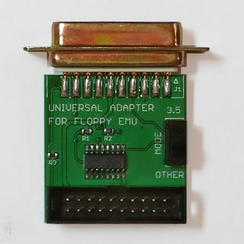
So how does the Universal Adapter work, and how does it differ from the Standard Adapter? The Standard Adapter is a passive device that maps the 19 pins of a male DB-19 connector to the 20 pins of a male 10×2 shrouded header. It rearranges the order of the signals on the pins, but it doesn’t alter them or affect them in any way. In contrast, the Universal Adapter is an active device with an on-board IC that helps with Apple II disk connections. Because the Floppy Emu hardware was originally designed for the Macintosh, it can’t handle some Apple II disk signals correctly, so the Universal Adapter does the necessary interface work. Depending on the switch setting, the disk drive enable signal from the computer may be modified before it’s passed on to the Floppy Emu, and some signals will be forced to different voltages.
It’s OK to use the Universal Adapter with a Mac or Lisa computer, even though it’s not needed for those systems – that’s why it’s called “universal”. People who use a single Floppy Emu board with both Mac and Apple II computers may find this convenient.
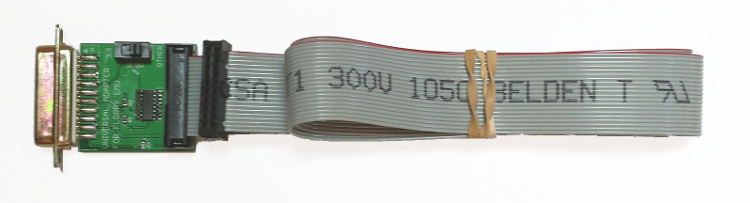
The Universal Adapter is available for sale now at the Floppy Emu product page. It includes a detachable three foot extension cable (about 1 meter), just like the Standard Adapter/Cable, and it’s available by itself or bundled with a new Floppy Emu board.
Read 2 comments and join the conversationWeb Hack Analysis, Part 3
Web Site Hacked
Web Hack Analysis Part 2
Web Hack Analysis Part 3
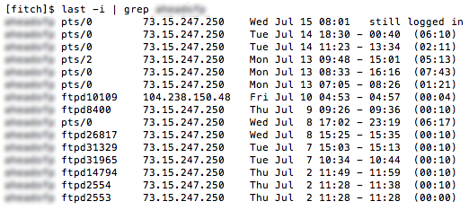
I believe I’ve identified how the hack on my websites occurred, and it wasn’t a WordPress vulnerability. It looks like the hacker got my Linux user password somehow, and then used ftp to login and modify the files on my web sites. Using the Linux command “last”, I generated a list of all logins from the past month, showing the method of login and the IP address. The result is shown above (I’ve blurred out my username because I’m starting to get paranoid, but it probably doesn’t matter).
There are lots of logins from 73.15.247.250 – that’s me. Some were console logins using ssh, and some were ftp logins. But on July 10 at 4:53 AM, there was an ftp login from 104.238.150.48. And not coincidentally, my site’s index.php file was modified 1 minute later, at 4:54 AM. Bingo.
Unfortunately the logs only go back a few days, so I can’t find any earlier instances of suspicious logins. And the FTP logs don’t even go back as far as July 10, so I can’t tell exactly what the hacker did when he connected by ftp.
So how did somebody get my password? Most likely it was due to my use of plain-old ftp for transferring files from my local machine to the web site, which sends my password over the internet in plaintext every time I log in. I knew it was insecure, but I did it anyway because it was convenient, and I figured “what could happen?” Well, this is what could happen. So I’ll be using sftp from now on.
If you’re a security guru or Linux know-it-all type, feel free to tell me what a dumb-ass I am. Believe me, I’m telling myself the same thing.
Read 7 comments and join the conversation