

In Search of the Elusive DB19
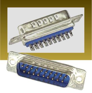
Discontinued parts are bad, “unobtainium” parts are worse. Floppy Emu uses a 19-pin D-SUB male solder cup connector, otherwise known as DB19P, to connect to the computer’s floppy port. DB19 connectors were never common, and were only used in 1980s and 1990s Macintosh, Atari, and some NeXT computers. Today in 2015 they’re very difficult to find. As far as I can tell they’re no longer manufactured, and are only available in small quantities from electronics surplus warehouses.
My hardware sales appear to be drawing down the remaining worldwide stock of these connectors. Working with the vendor who assembles the Floppy Emu boards, we’ve purchased the entire remaining stock from three surplus warehouses, and been advised that they won’t be getting any more. We have enough to finish the current batch of 100 boards, but after that it’s not clear if we can find more DB19s at a reasonable price, or at any price. Worst case, this will be the last batch of Floppy Emus, and I’ll have to stop selling them when the supply runs out. And a couple of DB19-based adapter boards I was planning to release will never see the light of day.
Vendors
Searching the web, it seems there are at least half a dozen places that sell DB19 male solder cup connectors. But if you look carefully, several of them are just alternate storefronts for the same company with the same stock. A few places show DB19 but list it as out of stock. At least one other shows it as in stock, but if you call them you’ll learn it’s actually not available.
These are the same vendor. I’ve bought their entire stock. They won’t be getting more.
These are the same vendor. Out of stock, not clear if they’ll be getting more.
Elliott Electronics Supply
Network Cables
These look like active vendors. I haven’t called yet to confirm availability or quantity in stock.
There’s one more vendor I won’t list here, because I don’t want other people buying up their stock. They’re kind of a pain to work with, but I’ve used their parts for all my boards thus far. Now they’re out of stock, and it’s not clear if they’ll be getting more, or if this is the end. Their web site says they are newly-manufactured parts, so I’m hopeful.
Options
A couple of other options, if the supply of DB19 connectors disappears:
- Use DB25 connectors, and cut off 6 pins. This might or might not fit, depending on the mounting screws and case cutout surround the DB19 port on each Macintosh model. It might be necessary to cut away part of the metal housing of the connector, using tin snips or a Dremel. It would be a lot of extra work, look ugly, and require a modification to the Emu’s PCB.
- Find an Asian manufacturer to make DB19 connectors. If I commit to buying enough of them, I bet I can find a D-SUB manufacturer in Asia who’d be willing to set up tooling machinery to build DB19s. I’m not sure how many I’d need to buy, though – thousands? And I’m not sure how to find potential Asian partners, and make a proposal to them. My first thought is to use Alibaba to identify existing D-SUB manufacturers of other sizes.
Sorry Pakistan (Why PayPal Stinks)

I use PayPal to accept payment for all BMOW products. Customers can create a PayPal account and send money from their account balance, or they can use PayPal with a Visa credit card to send payment directly without creating an account. That’s mostly worked OK, but today I learned that PayPal straight-up denies all credit cards from Pakistan, no exceptions. It’s like a giant middle finger, extended to an entire country of 182 million people. In fact there are 18 countries where PayPal won’t accept payments, some of which would probably never be customers of mine anyway (Papua New Guinea?), but with over 100 million people and English as an official language, the absence of Pakistan is especially galling.
PayPal is popular, at least in the United States, and it’s convenient, but it can also be infuriating. They act like a bank, and hold balances and perform money transfers like a bank, but aren’t subject to the same regulations as a bank. The internet is full of horror stories where PayPal froze accounts containing thousands of dollars due to “suspicious activity”, with no path or process for people to appeal or even discuss it with a human being. And from a seller’s point of view, the PayPal dispute resolution process is as bad as it gets. If you want to scam me, just buy a Floppy Emu, and when it arrives file a PayPal dispute saying that the item was not as described. You will get your money refunded 100% of the time and end up with free hardware, and there’s nothing I can do about it. (Please don’t actually do this.)
Unfortunately there are no realistic alternatives to PayPal that provide similar capabilities. WePay is US-only. Square is only slowly expanding outside the US. Amazon Payments is a mess. Too many companies seem to believe the world consists of the United States and “miscellaneous other”, a group of 6.7 billion people who are somehow not very important.
After some investigation, it looks like the best solution for a one-time payment from Pakistan to the United States is a money transfer service like Western Union or MoneyGram, even though they charge a 10% commission. It’s OK for a one-off, but if I were receiving a lot of orders from Pakistan, it would be a poor long-term solution. If anyone has experience with sending money from Pakistan to the USA and can suggest a better method, I’d be happy to hear about it.
Read 8 comments and join the conversationBoard Assembly Headaches
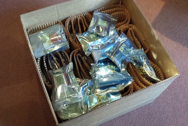
This is what 100 unsaleable Floppy Emus look like. After six weeks of waiting, today I received the new batch of assembled boards, and eagerly opened the box. Excitement gave way to dismay when I discovered that every one of them was assembled incorrectly. Arghh, noooooo! I’ve been unable to fill any orders since mid-December, so I’d been counting down the days until the new hardware was expected to arrive. Now it looks as if there will be a further delay of about a week. Manufacturing is hard.
For whatever it’s worth, my instructions were correct and the error was the fault of the assembly shop. That means I won’t have to pay to fix the mistake, but it doesn’t help me get corrected boards any faster.
The assemblers transposed a part from the extension cable’s IDC20 to DB-19 adapter onto the main Floppy Emu board itself, and also omitted one component. The resulting boards still work, but won’t fit the Floppy Emu cases, and I’m left without any usable extension cables. After some discussion on how to make things right, I agreed to return the whole batch to the assembler, and they’re going to rework the boards to the correct design. I’m not certain how long that will take, but I expect it should be finished by next week.
I could demand that they replace the entire batch with new parts, or give me the batch for free, but I don’t think that would go well. Like me, they’re a small business, and I don’t want to stiff them for thousands of dollars in losses if they can make good on their mistake through rework. And quite frankly I’m lucky they accept my business at all, since my order sizes are so small compared to their typical jobs. If I stomp my foot and demand a pound of flesh, I may get it, but I may also be asked to bring my future business elsewhere. I like working with this shop – they’re reasonably priced and local – and I’d hate to start over from scratch building a relationship with a new assembler in some far-off location. So for now I’ll wait, impatiently.
Read 16 comments and join the conversationMake Your Own Katy
If you’re crazy enough to want to build your own 68 Katy, I’d like to help you do it. The PCB version is the easiest way to get started. Compared with the breadboard version, it replaces all of the glue logic, timers, and other miscellaneous components with a single CPLD. The number of status LEDs is also reduced from eight to one, and there’s a small change to the serial status address mapping. Otherwise it’s functionally identical to the original breadboard prototype. Get a PCB, solder the components, burn the ROM, and you’ll be in business.
Assembling the PCB requires soldering one surface mount component, the 44 pin CPLD in TQFP package. It can be soldered with a standard iron using the drag soldering method (my preference), with hot air, or with a toaster oven reflow. The rest of the components are easy through-hole parts.
You’ll need an EPROM burner to program the initial flash ROM data, as well as a JTAG programmer for the CPLD. I used a Bus Pirate with the XSVF player firmware to program the CPLD.
Note that the PCB and breadboard versions of 68 Katy are not binary compatible, due to a small difference in their memory maps. If you’re building the PCB version, be sure to use the files linked here, and not the breadboard version files.
PCB Version: Parts List
- Motorola 68008 CPU, 8 MHz, 48-pin DIP package
- AM29F040B or SST39SF040 4 megabit Flash ROM
- BS62LV4006PIP55 4 megabit SRAM, or compatible substitute
- Xilinx XC9536 CPLD – not XC9536XL
- Sparkfun FT245RL USB to FIFO breakout board
- 12 MHz metal can oscillator
- bypass capacitors, resistors, LEDs, buttons, switches, sockets, etc. – complete parts list
PCB Version: Files
- schematic and board layout – Board definition in KiCad format
- Gerber files – For getting a copy of the PCB made at a fab like Seeed Studio
- CPLD source – Xilinx ISE project and Verilog source code for the CPLD
- 68katy.xsvf – JTAG configuration file for the CPLD
- monitor.asm – My ROM-based monitor/bootloader program. I used Easy 68K to assemble it.
- monitor-plus-linux-pcb.bin – This is the final binary image I programmed into the flash ROM, containing the monitor/bootloader program with the uClinux kernel concatenated to it beginning at address $003000
- virtualboxes.org Ubuntu machine – For Linux cross-development, I used Ubuntu 12.04 32-bit running as a virtual machine under Virtual Box. Don’t use the 64-bit version, or the 68K toolchain won’t work. You can use this pre-configured Ubuntu Virtual Box machine image. Username “ubuntu”, password “reverse”
- uClinux-dist-20040218 – I started from the February 18, 2004 release of uClinux. This is the unmodified version.
uClinux-20040218-pcb.tar.gz – This is my modified version of uClinux. It includes code for kernels 2.0, 2.4, and 2.6, but I only ported kernel 2.0 for 68 Katy. Search the code for “68KATY” to find my changes. - m68k-elf-tools-20030314 – You’ll need a 68K cross compiler and other tools in order to build the uClinux source code. I used m68k toolchain 20030314. It’s supposed to be a self-extracting shell script, but that didn’t work for me. I had to extract it manually, like this:
user@ubuntu$ tail -n +43 m68k-elf-tools-20030314.sh | gunzip > tools.tar

user@ubuntu$ tar xvf tools.tar
Startup
Assemble the PCB. Attach a regulated 5V power supply, and turn on the power switch. Use the Bus Pirate or another JTAG programmer to program 68katy.xsvf to the CPLD – the board must be powered when you do this, but components other than the CPLD don’t necessarily need to be present yet.
Use an EPROM burner to program monitor-plus-linux-pcb.bin to the flash ROM, then place the ROM chip in the board’s socket. Place the CPU and RAM in their sockets as well.
Attach a USB cable to the FT245RL module, and plug it into your computer. The FT245RL module doesn’t need to be connected to the 68 Katy board yet – it’s powered by the USB cable. If necessary, install the FTDI virtual serial port driver software for your computer. When complete, your should see a new virtual serial port like COM4. Now place the FT245RL module in its socket on the 68 Katy board.
Turn on the 68 Katy board. Use terminal software like Tera Term to open the serial port where the FT245RL is connected. The serial port speed and parity settings actually don’t matter, although choosing a faster speed will result in faster file transfer times when sending updates to the board.
Press the RESET button on the 68 Katy board. If everything is working, you should see the monitor prompt zBug(ROM) for 68Katy (press ? for help). Press ? to see a list of available commands. The monitor can load Motorola S-record files, view or disassemble memory, and many other useful things. The uClinux image is stored in the flash ROM beginning at address 003000 hex. To start Linux, from the monitor prompt type j 003000.
Using the provided source code, you can modify the monitor program, the uClinux filesystem contents, or the uClinux kernel. Use a hex editor or other tool to concatenate the uClinux image file 68katy.rom to the monitor program monitor.bin. The combined result must be no larger than 480K. Note that 68katy.rom itself is a concatenation of the uClinux kernel code kernel.text, kernel initialized data kernel.data, and the read-only Linux filesystem image romfs.img. To update the flash ROM with the new monitor or uClinux, from the monitor prompt type u, then use the terminal software’s file transfer option to download the concatenated file. If using Tera Term, make sure to select the option to send the file in binary format, not text.
Have fun!
Read 23 comments and join the conversation68 Katy PCB Style
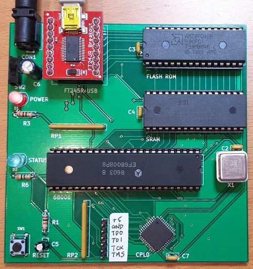
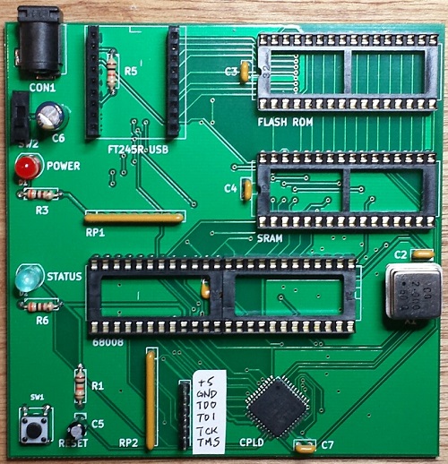
The 68 Katy PCB version is working! Mostly! I’ve had the parts and PCB on hand for a while, but only recently got around to assembling and testing the thing. Now instead of a breadboard that runs uClinux slowly, I’ve got a 10 x 10 cm PCB that runs uClinux slowly. Ah, the sweet taste of success.
Assembly
The assembly process went smoothly, even though I forgot to label some important items on the silkscreen like the JTAG pins. Revision 2 can fix that. The only real soldering challenge was the Xilinx CPLD, a 44-pin SMD chip. The PCB footprint for the CPLD wasn’t the best, as the pads were barely any larger than the pins themselves, making it somewhat difficult to solder with an iron. But thanks to my experience hand-soldering hundreds of similar chips with Floppy Emu, I was able to use a drag soldering technique to get the CPLD down with only minor rework required. The rest of the through-hole components were quick to solder, and I finished the board off with a fancy blue status LED.
Since I don’t own a Xilinx programmer, I used a Bus Pirate to program the CPLD. The process isn’t too bad for occasional or emergency use. Using the Xilinx IDE software, you can create a .xsvf programming file for your design and the target chip type. Then you flash a special XSVF player firmware onto the Bus Pirate, connect the BP’s pins to the JTAG header on your board, and finally run a Windows utility to program the .xsvf file to the chip. I was stuck for a while at the point of flashing the alternate firmware to the Bus Pirate, since I’d forgotten that you must manually invoke the bootloader before updating the BP’s firmware. Once I figured that out, the actual CPLD programming was quick.
Boot Up
I pulled the 68008 CPU, RAM, and ROM from the breadboard, stuffed them into the sockets on the new PCB, and confidently flipped the power switch. Oh my eyes, that blue LED was blinding! Who chose that thing?? I tried to take a photo of it, but it’s so overwhelming that it just looks like a white dot on a dim background. Next time I’ll stick with red, but for now I think I’ll need to wear sunglasses when using this thing. 🙂
Of course the board didn’t work. When powered on, it appeared to do nothing at all. I poked and prodded for a while with a logic probe, and all the signals seemed to be behaving normally. I don’t know why I always fall back to the logic probe, when I’ve got two logic analyzers and an oscilloscope that would give me much better information, but somehow those tools always feel like too much hassle to get out and set up.
After a few minutes I remembered that I’d made a small change to the address map for the PCB version, so the software for the breadboard version won’t be directly compatible. In order to save CPLD pins and board traces, I changed the way the RDF and TXE status bits are read from the FT245 USB FIFO. In the breadboard version, these status bits appear in different bit positions at a single memory address. But in the PCB version, they appear in bit 0 of two different memory addresses. Both my monitor program and my uClinux FT245 driver needed to be modified to reflect this change.
BREADBOARD 68 KATY               PCB 68 KATY
00000 - 77FFF : ROM              00000 - 77FFF : ROM
78000 - 79FFF : serial in        78000 - 79FFF : serial in
7A000 - 7BFFF : serial out       7A000 - 7BFFF : serial out
7C000 - 7DFFF : serial status    7C000 - 7CFFF : serial status RDF
                                 7D000 - 7DFFF : serial status TXE
7E000 - 7FFFF : LED register     7E000 - 7FFFF : LED register
80000 - FFFFF : RAM              80000 - FFFFF : RAM
Once I made that fix, the board was up and running! I played with the monitor program, booted uClinux, and played Adventure. Everything seemed solid.
“Mostly”
The breadboard version of 68 Katy ran at 2 MHz, and didn’t work at higher speeds. I initially tried the PCB version at 2 MHz as well, and everything was great. But when I tried faster speeds like 6 or 8 MHz, it didn’t work at all — it just did nothing, or spewed endless garbage characters. I was disappointed, because I’d hoped the cleaner signals on the PCB vs the breadboard would enable the computer to run at higher speeds.
But wait! After a lot of fiddling around, I discovered that the PCB version of 68 Katy had no trouble running at higher speeds, it just had trouble resetting at higher speeds. If I moved my hand around the CPU while repeatedly pressing the reset button, eventually it would work and the monitor prompt would appear. After that everything was fine, and I could use the monitor program without trouble, or boot into uClinux and play Adventure or run vi. I successfully tested the hardware at 2, 4, 6, and 8 MHz. As long as I could get it to reset cleanly, then it ran flawlessly.
So what’s going on? By touching different CPU pins with my finger, I think I’ve narrowed the problem down to either the /IPL2 interrupt pin, the /RESET and /HALT pins, or the reset button debounce circuit. /IPL2 is the 100 Hz timer interrupt, and it seems like maybe the CPU is immediately hitting an interrupt the instant it comes out of the reset state. Since the interrupt vectors haven’t been initialized yet, it crashes. That does’t fit what I know about the 68008, though – the datasheet says interrupts will be disabled after a CPU reset. Maybe there’s a bug in my monitor program that enables interrupts before the vectors are initialized, but I double-checked and didn’t see anything like that. Anyway, it’s the same monitor program that worked fine on the breadboard.
A more likely explanation is a problem with the reset signal itself. The board has a pushbutton with an RC debounce circuit, with the pushbutton signal connected to a CPLD input. The CPLD uses that to generate the /RESET and /HALT signals for the CPU, which are a little bit strange in the 68000 family. In order to reset the CPU, both /RESET and /HALT should be pulled low. But to exit the reset state, /RESET and /HALT should be allowed to float, and pulled high with an external pull-up resistor. That’s because those signals are actually bidirectional, and are sometimes pulled low by the CPU itself. On the 68 Katy PCB, both signals have independent 10K pull-ups to 5 volts. The CPLD code looks like this:
assign _reset = button ? 1'bZ : 0;
assign _halt = button ? 1'bZ : 0;
Maybe /RESET and /HALT aren’t being deasserted at the same time? Or maybe the rising edge on the pushbutton signal is too slow, and the signal lingers too long in the forbidden voltage zone between logical 0 and 1, causing problems? Indeed, if I monkey with the pushbutton circuit to reduce the RC time constant, it seems to help somewhat, but maybe that’s a red herring.
Maybe the action of the charging/discharging capacitor in the pushbutton circuit is causing some electrical noise that messes up the CPU?
The question is why any of these problems would be worse at higher clock speeds. At 2 MHz, the board runs fine. At 4 MHz, the board fails to reset properly about half the time. At 6 MHz, the board virtually never resets properly, unless I run my finger back and forth across the CPU pins while repeatedly pressing the reset button. 8 MHz behaves even worse than 6 MHz. This must be a clue…
Read 12 comments and join the conversationSaleae Pro 8 Logic Analyzer Review
When Saleae’s first USB-based logic analyzer burst onto the electronics scene in 2008, it was praised for its ease of use and low cost. For 2014 the company revamped its product line, replacing all its existing models with four new products. Last month the nice folks at Saleae were kind enough to send me a new Logic Pro 8 for review, so I recently had a chance to test the hardware first-hand. In brief, it’s well-polished and good at what it does, though I wish it did more.
But first – what’s a logic analyzer? Much like an oscilloscope, an LA is a tool for examining electrical waveforms in a running circuit – the so-called “device under test” or DUT. But where an oscilloscope is used to view analog waveforms with a continuously varying voltage, a logic analyzer displays digital waveforms whose value is either 0 or 1. Most oscilloscopes have two channels, but typical LAs have at least eight channels, and sometimes 40 or more. An LA also includes powerful software for triggering, decoding, and dissecting the collected data. If you do any kind of digital electronics work, a logic analyzer is indispensable.
In the old days, an LA was a stand-alone tool, like my ancient HP 1631D. Modern LAs such as Saleae’s are more likely to be PC peripherals consisting only of the signal acquisition hardware, with all the display and analysis work handled by a software program on the PC.
Specs
The Logic Pro 8 is the second from the top in Saleae’s product lineup, which also includes the Logic 4, Logic 8, and Logic Pro 16. Priced at $399, it’s an 8 channel logic analyzer with a max sampling rate of 500 Megasamples/sec, though when using all 8 channels the max sampling rate is reduced to 100 MS/sec. The Logic Pro 8 uses USB 3.0 to push all that sample data to the PC at high speed.
Saleae recommends a minimum of 4x oversampling when capturing digital signals, so 100 MS/sec is enough to reliably capture data from digital systems with signal speeds up to 25 MHz. With four or fewer channels in use, the full sampling rate of 500 MS/sec is possible, allowing capture of digital signals up to 125 MHz. It’s important to remember that these are signal speeds, not CPU core speeds. The Beaglebone Black may have a 1 GHz processor, but its GPIO signals will normally be changing state at a few tens of megahertz at most. I’ve personally never built a digital system with external signal speeds above 5 MHz. 100 MS/sec will be more than enough for most hobbyist purposes.
Unique among the competition, all the new Saleae models except the Logic 4 feature input channels with dual digital/analog capability. Each channel can be configured as a digital input, an analog input, or both simultaneously. The analog sample rate is limited to 50 MS/sec with up to three channels, with a bandwidth of only 5 MHz, so it’s not going to replace a bench oscilloscope. But as a quick sanity check for what’s happening in the analog domain for low-speed signals, it’s a nice addition.
Unlike some other logic analyzers that feature external clock and trigger inputs, 8 channels on the Logic Pro 8 means 8 total inputs. There’s no support for external clocking, which is a disappointment. None of the current Saleae LA models have external clock inputs, and they’re the only logic analyzers on the market I’m aware of that lack this feature. I hope to see an external clock and trigger added to Saleae’s future products.
The Pro 8 supports logic levels between 1.2 V and 5.5 V for digital signals, with user-selectable threshold voltages. In analog mode, the input voltage range is -10 V to +10V. Analog signals are captured at 12-bit resolution.
Sample Streaming
All of Saleae’s logic analyzers are streaming samplers, an important detail that affects how they perform. A streaming sampler is essentially the opposite of the more familiar buffered sampler design. Buffered logic analyzers contain dedicated high-speed memory for storage of signal data. Typically the memory is enough to hold a few thousand sample points, and when it’s full, signal acquisition stops. The acquired data is then displayed and analyzed as a post process.
In contrast, a streaming sampler has little or no built-in memory. Sample data is streamed over USB in real-time to the connected PC, where it’s stored in RAM or on the hard disk. This enables huge signal captures containing millions of samples, much larger than what’s possible with a buffered sampler. But when using many channels and high sample rates, streaming can overwhelm the PC’s available USB bandwidth, resulting in failures. Faster PCs and a USB 3.0 connection both help. This design explains why streaming samplers generally don’t have more than 8 or 16 channels – there just isn’t enough USB bandwidth to stream more channels in real-time.
Unboxing and Setup
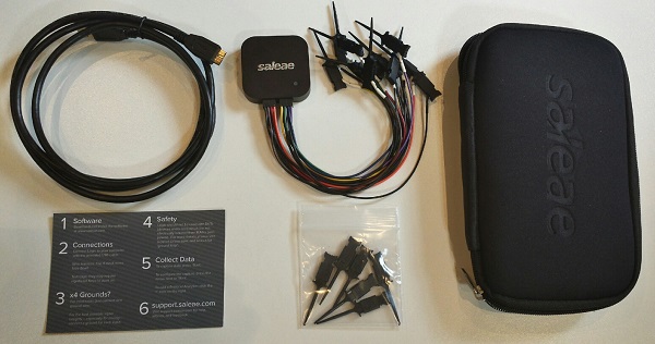
The Logic Pro 8 seems impossibly small – just a two inch square aluminum puck. It comes packed with a USB cable and two flying lead wiring harnesses, containing eight signal wires and eight ground wires. The wires are terminated with a female 0.1 inch connector, which can be plugged directly onto standard male headers, or connected to one of the 16 included IC test hooks. The whole setup packs away into a cushioned nylon carrying case. It’s all quite nice, and the value of the included accessories is something to consider when comparing the Logic Pro 8 to its competition.
The Logic is so small and light, it can get lost on a desk, or pulled off the desk by the weight of the cables attached to it. This is one instance where Saleae may have too much of a good thing, and a bit of extra size and weight might be welcome.
I was slightly confused by all those ground wires at first. According to Saleae, it’s only necessary to connect one of the ground wires for most applications, but for best results with analog sampling all the ground wires should be connected.
There’s no software CD included with the Logic Pro 8, and only a small quick start card that advises readers to visit www.saleae.com for instructions and software. No matter, anything they included in the box would likely be out of date by the time it was opened anyway.
The client software runs on Windows, Mac OS X, or Linux, and downloading was easy, with no registration or other annoying hoops to jump through. I was surprised by this pop-up, though:
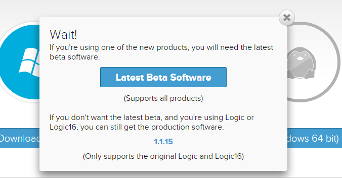
You must use a beta version of the client software if you have one of the current Logic models, including the Logic Pro 8. The release/stable version of the client software only supports the older, discontinued models. I’m probably reading too much into the word “beta”, and Google has conditioned us all to be comfortable with software in perpetual beta, but this strikes me as a little strange. Supplying unfinished beta software to customers who’ve paid up to $499 for Saleae’s latest and greatest hardware risks annoying those customers and spoiling goodwill. Fortunately, Saleae’s customers seem to be an understanding bunch.
Once downloaded, the client installs a Saleae USB driver as well as the actual client application. There aren’t any configuration choices to make, so the whole installation process is quick and painless. Within a few minutes of opening the box and downloading the software, everything is set up and ready to use.
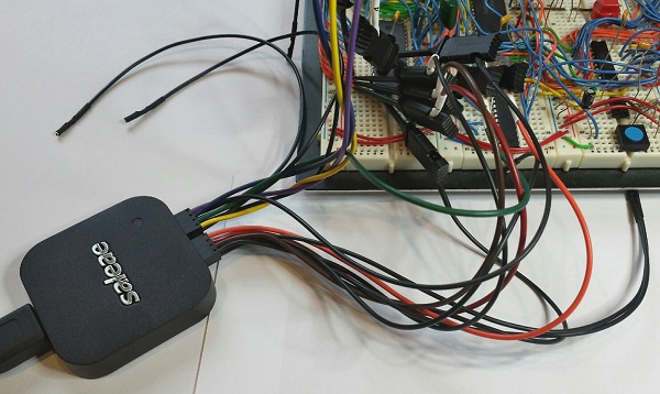
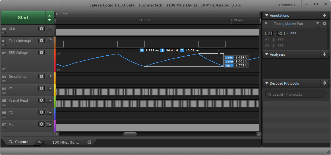
Working with the Logic
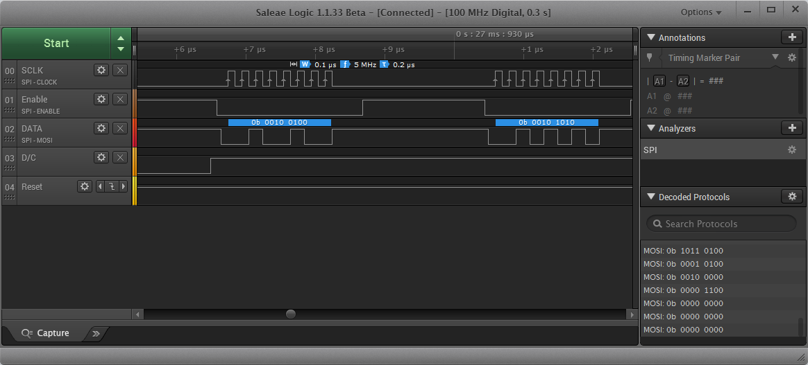
For basic setups, capturing and analyzing data with the Logic Pro 8 is simple. Just connect the ground and signal wires to the device under test, hit the friendly green “start” button, and in a few moments you’ll have a screen full of waveform data. Digital and analog data are displayed on the same screen, with the same time scale. From here you can zoom in and out of the captured waveforms, or pan left and right to view different time periods. The zooming and panning is all very smooth and quick.
Viewing a group of assorted waveforms is all well and good, but the real strength of a logic analyzer comes from the “analyze” part of its name. The Saleae client software includes several built in protocol analyzers that can extract high-level data from raw waveforms. For example, the async serial protocol analyzer can reconstruct a serial byte stream from raw RS-232 data on a channel. Tell the analyzer which channel to examine, and the bit rate and parity settings, and it does the rest. The decoded serial data is displayed as an annotation overlay on the raw waveform, and also in a table view. The current version of the software contains over 20 protocol analyzers, including async serial, I2C, SPI, JTAG, MIDI, simple parallel, and many others.
Digital and analog sample rates can be adjusted independently, and the total capture length is also selectable. Unused channels can be turned off. In general, the fewer channels that are used, the higher the sampling rate that the Logic Pro 8 can achieve.
For the basic use case of grabbing some signals and eyeballing what’s happening, the Logic Pro 8 is excellent. It’s amazing how smooth and easy the whole process is, especially compared to other logic analyzers that might have similar specs. Navigating through the waveforms is a pleasure, and helpful measurement cursors pop up wherever you place the mouse pointer. It’s really a pleasure to use.
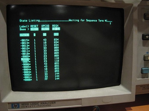
One missing feature I’d really like to see is a state mode, or state table view. With a complex system, I often find it’s easier to view things as a list of consecutive states, with one state per line, rather than as a collection of individual waveforms plotted against a time axis. The Saleae software does have a list panel showing the protocol analyzer results, but there’s not much functionality to it. When I’ve worked with other logic analyzers in the past, I spent almost all my time in the state view, and almost never looked at the waveform time view. Saleae needs to expand the existing list panel into a full-fledged data view screen, with functionality similar to the waveform view. Here’s what state view looks like on my old HP 1631D:
One minor gripe is the lack of a continuous capture mode. When you press the start button, the client software will capture one buffer’s worth of data, display it, and then stop. Sometimes it’s helpful to use a logic analyzer to do continuous capturing like an oscilloscope, many times per second, constantly updating the results on screen. If you’re capturing the same event over and over, this makes it easy to see if any event is different from the others, or if there’s timing jitter. Unfortunately the Saleae software doesn’t support continuous capturing.
I did experience some software problems during my testing, and the client lived up to its “beta” label by crashing several times. Most of these only required relaunching the client software, and submitting a crash report to Saleae. But in one instance, a crash somehow left my USB mouse and keyboard in an unresponsive state. Even though the PC was still running, I was forced to do a hard reset of my PC.
Triggers
What about more complex signal capture scenarios, requiring a trigger? Pressing a button to begin an immediate signal capture is OK if you’re confident the event of interest will be somewhere in the captured data – either because it happens repeatedly, or you can force it to happen when desired. But many times it’s necessary to define a custom trigger to begin signal capture only when a particular event happens – say a specific value appears on a bus, or a rare error condition occurs.
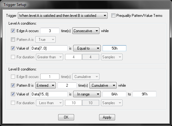
I was disappointed to discover the Saleae software only supports fairly rudimentary triggering. Similar to an oscilloscope, it can trigger on a rising or falling edge on one channel, optionally requiring a specific hi/low level on other channels. That’s insufficient for capturing complex or rare events. Most other logic analyzers I’ve seen support a large array of different triggering options, like triggering when a bus or serial value is or isn’t present, or is in a particular range, or a set of conditions happens N times consecutively, or logical and sequential combinations of multiple individual trigger clauses. For example, here are the trigger setup options for the Intronix LA1034 LogicPort, a Saleae competitor:
The lack of triggering options may be a result of Saleae’s streaming sampler design. The acquisition hardware is essentially just a high speed data collection port, and it may lack the necessary smarts to check for trigger conditions in real time. From reading Saleae’s support forums, it appears that triggering is actually performed in software on the PC, rather than in hardware. I would have thought that would make it easy to support complex triggering options, but apparently the software isn’t able to compute complex triggers in real time either. In fact, even simple triggers have major problems on the new Saleae hardware. According to the support forums, if any analog channels are in use, the software can’t keep up with incoming sample data while also checking for a trigger condition. It falls further and further behind, and the client’s memory use balloons until it crashes. The Saleae engineering team is working on a fix, but for now their advice is to turn off analog channels when using triggers.
The absence of robust triggering options might not be too bad if it were possible to search the acquired data for a complex trigger-type event after the fact. Instead of triggering on an error condition, you could capture 10 million sample points, and then search for the error condition in the captured data. The Saleae client software does have a basic search capability, so for example you can look for all instances where the value 0xC8 appeared on the serial port. But there’s no capability to search for multi-byte sequences, or combinations or sequences of conditions, or any of the complex trigger conditions mentioned earlier. In a pinch, the captured data can be exported to Excel, where other tools can be used to search, but that’s not a great solution if it’s something you’ll need to do regularly.
External Clocks
Earlier I mentioned that the Saleae LAs don’t have external clock inputs. Why should you care about external clocks? The first reason is speed. When using an external clock (the DUT’s own clock), 4x oversampling isn’t necessary, and it’s possible to capture digital signals all the way up to the LA’s max sample rate. A 100 MS/sec logic analyzer using an external clock can capture digital signals at speeds up to 100 MHz. Exactly one sample is taken per clock cycle, on the clock edge. Without an external clock, 4x oversampling is required, and 75% of the LA’s potential performance is effectively thrown away. In practice you might be able to get away with 2x oversampling and only pay a 50% penalty, but the cost is still too high.
The second reason that external clocks are important is correctness of the captured data. With external clocking, samples are taken exactly at the clock edge, and the values captured are those that were seen by synchronous devices at the clock edge. Without an external clock, samples will be taken some unpredictable amount of time before and after the clock edge, and the true value at the clock edge can’t be known.
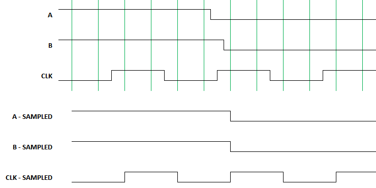
Consider a system with two digital signals, A and B, and a separate clock signal. Imagine that the Logic Pro 8 is sampling these three signals four times per clock period, for 4x oversampling, at intervals shown by the green vertical lines. A has a transition shortly before the second rising clock edge, and B has a transition shortly after the edge. But when sampled by Logic and displayed in software, both A and B will appear to transition coincident with the clock edge. What were the actual values of A and B at the clock edge? We can’t tell.
To be fair, the speed penalty described here may not be an issue in most cases. The Logic is fast enough, and the digital signals are slow enough, that a 75% speed penalty isn’t fatal. Likewise the correctness problem may not be an issue in most cases either, as long as signals don’t change values too close to a clock edge, where “too close” means within one sample period. The average person using the Logic Pro 8 to debug a low-speed I2C communication stream won’t have any problems. But when pushing to higher speeds with tighter timing margins, the lack of an external clock is a real handicap.
Analog
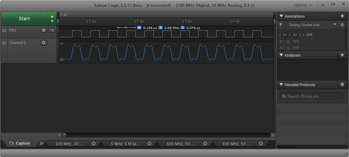
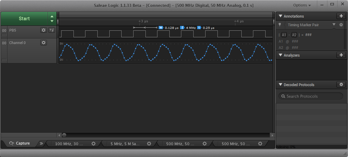
To test the Logic Pro 8’s analog input capability, I used a microcontroller to generate a square wave at a few different frequencies, and then viewed it as both a digital and an analog signal. The Logic Pro 8 samples analog inputs at 50 MS/sec, with a 5 MHz analog bandwidth. When examining a 2.66 MHz digital square wave as an analog signal, there was a pronounced ringing and smoothing of the displayed analog waveform, and it didn’t look much like a square wave anymore. At 4 MHz, the analog waveform just looked like a sine wave.
I had initially assumed the analog inputs would be most useful for checking the signal integrity of digital signals – looking for overshoot, noise, or glitches that might cause problems. But given the very low bandwidth of the analog inputs, it’s just not possible to see useful analog domain details, even with low-speed digital signals. So scratch that idea.
What are the analog inputs good for, then? If you’re working on an audio-related project, the analog inputs are plenty fast enough to handle audio frequency analog signals. Or if you’re interfacing with an analog sensor, such as a light or force sensor or a capacitive touch sensor, the analog inputs will come in handy too. For the vast majority of projects, though, I suspect the analog inputs will go unused.
Plugins and Scripting
The Saleae client software offers two ways to extend its functionality: protocol analyzer plugins, and client scripting. Plugins are implemented as C++ shared libraries, and enable the client to be extended to support new protocols, or to add new options to existing protocols. Need decoding of NRZI serial data from a floppy disk? Add it yourself! This capability looks like it’s still a work in progress, and the support page lists a number of incompatibilities between analyzer SDK versions and client versions, and custom analyzers currently aren’t supported with the 64-bit Windows client.
The scripting API enables users to programmatically configure the client software, and trigger captures. Just open TCP socket 10429 on the client PC, and send text commands to control the running client. Because it’s a text-based protocol using a standard socket interface, the test script can be written in any language. This interface is great for using the logic analyzer as part of an automated test framework.
Saleae Logic Analyzers, Past and Present
The original 8 channel Saleae Logic was introduced in 2008, and was later followed by the Logic 16. These remained Saleae’s only LA products until 2014, when they were discontinued and replaced with four new models. The new models offer analog sampling and faster sample rates, but at higher prices than the models they replaced.
| Model | Price | Availability | Channels | Analog | Sample Rate, 3 channels |
Sample Rate, all channels |
| Logic | $149 | Discontinued | 8 | No | 24 MS/s | 24 MS/s |
| Logic 16 | $299 | Discontinued | 16 | No | 100 MS/s | 12.5 MS/s |
| Logic 4 | $99 | Available | 4 | 1 | 12 MS/s | 12 MS/s |
| Logic 8 | $199 | Available | 8 | Yes | 100 MS/s | 25 MS/s |
| Logic Pro 8 | $399 | Available | 8 | Yes | 500 MS/s | 100 MS/s |
| Logic Pro 16 | $499 | Available | 16 | Yes | 500 MS/s | 100 MS/s |
It’s not clear to me that the current Saleae models are a better value than the discontinued ones. If you don’t care much about analog capability, than the original 8-channel Logic model at $149 was probably a better deal than the current Logic 8 at $199. For people who need more channels, the Logic Pro 16 is clearly more capable than the Logic 16 that it replaced, but at a 66% higher price it’s only a good deal if you actually need those extra capabilities. For electronics hobbyists working with relatively slow parallel bus-based systems, the old Logic 16 was ideal. The Logic Pro 8 stands out somewhat awkwardly on the price/performance scale. At twice the price of the similar Logic 8, and 80% of the price of the Logic Pro 16, it’s hard to see why anyone would choose it.
If I were Saleae, I would bring back the original Logic and Logic 16 models, selling them alongside the new models. The original models are both good logic analyzers, representing different cost vs performance tradeoffs than those offered by the current models. And I would cut the price of the Logic Pro 8 to $299, to make it more competitive with the rest of the product lineup.
Competing Models
How do the Saleae logic analyzers stack up against low-cost LA solutions from other vendors? I haven’t used any of these logic analyzers directly, but I’ve experimented with the client software for each one and dug through their documentation, to get an idea of their capabilities.
USBee SX and ZX – $169 and $495
These are 24 MS/sec 8 channel streaming samplers like the original Saleae Logic. Unlike the Saleae units, the USBee LAs feature external clock and trigger inputs in addition to the 8 data channels. The USBee client software has similar features to the Saleae client, with equally weak triggering options. The software feels fairly clunky and awkward, although it does have a state view mode. As far as I can tell, the ZX is just the SX with more powerful software. My overall impression of both models is not great.
Intronix LA1034 LogicPort – $389
This is a 500 MS/sec 34 channel buffered sampler. It can also do 200 MS/sec state mode with an external clock. Unlike the Saleae LAs, the advertised 500 MS/sec isn’t for just a few channels, but is available when using all 34 channels. The sample buffer holds up to 2K samples, or more if using sample compression. That’s still puny compared to the millions of samples you get with the Saleae units, but it makes up for it with powerful triggering options, so you can capture only the specific event of interest. The software isn’t as pretty as the Saleae client, but it’s quite useable and powerful, with a nice state view mode and many other advanced capabilities. The only thing I noticed missing is a search feature, although with only 2048 samples there’s not so much to search. I’ve never heard of Intronix before, but the LA1034 is enthusiastically recommended in a couple of electronics forums.
Open Logic Sniffer – $50
The OLS is an open source hardware product, designed by the Gadget Factory and Dangerous Prototypes, and sold by Seeed Studio. It’s a buffered sampler, configurable as a 200 MS/sec 16 channel LA with 8K sample depth, or a 100 MS/sec 32 channel LA with 4K sample depth. The price is a bit misleading, since it’s just a bare circuit board sold without a case or test leads, but a complete setup can be put together for about $75. It supports external clock sources, and has fairly powerful triggering options, but lacks a state view mode. The popular “JaWi client” software is a little funky compared to the polish of Saleae’s software, but for an open source product it’s pretty good. The Achilles’ heel of the OLS is the documentation and setup. Documentation is a confusing tangle of wikis and docs and versions, scattered across three different web sites, with redundant or conflicting information, and frequent links to obsolete information. When you do find what you’re looking for, it’s hard to know if it’s authoritative or current. But for those willing to endure a product that’s rough around the edges, the OLS may be a worthwhile option.
DS Logic – $99
Begun as a Kickstarter project in 2014, the DS Logic is a 16-channel buffered sampler with a hefty 16M sample depth. It samples digital data at rates up to 400 MS/sec, or 100 MS/sec when using all 16 channels, and also includes external clock and trigger inputs. The client software is very similar to Saleae’s – they practically cloned the UI – but it adds a few extra features like advanced trigger options and continuous capture. A $299 deluxe version adds an analog oscilloscope function with 30 MHz bandwidth, and wireless data collection capability.
Conclusions
Saleae Logic Pro 8 – Likes
- Hardware quality
- Ease of setup and use
- Huge capture sizes
- Extensible client software
Saleae Logic Pro 8 – Dislikes
- No external clock input
- Low analog input bandwidth
- No state view
- Limited trigger/search options
- No continuous triggering
So does the Saleae Logic Pro 8 get BMOW’s recommendation? Not quite. It’s a nice piece of hardware with well-polished software, but it’s missing some key logic analyzer functions, and doesn’t offer enough extras compared to cheaper LA models to justify its $399 price tag. For basic electronics hobbyist use, I would instead recommend the Saleae Logic 8 at $199, or either of the two discontinued Saleae models if you can still find them. For more complex work requiring higher speeds, more channels, or non-trivial triggers, the LA1034 LogicPort, Open Logic Sniffer, and DS Logic all offer more functionality for the same price or less, although with less polished software. I’m looking forward to Saleae’s future hardware updates and especially their future software improvements, since three of my dislikes could be addressed entirely in software. We live in interesting times, and it’s exciting to see what the tool vendors will dream up next.
Read 19 comments and join the conversation