

Manufacturing is Hard
There’s a big difference between building one of something, and making a repeatable process to build 10 of them, or 100. Unfortunately I’m learning that the hard way while I try to get some more Floppy Emu boards ready to sell. If I had any hair, I’d be pulling it out! I never thought this would be so hard.
If you haven’t been following the earlier posts, Floppy Emu is a floppy disk drive emulator for vintage Macintosh computers. I built the first Floppy Emu for my personal use about a year ago, and while the soldering was a little challenging, everything worked once it was done. I posted the design on the BMOW web site, and since then I’d estimate about 10 other people have built their own Floppy Emu boards. Then in October I built two more boards from my remaining parts stock, and sold them on eBay. I tested those thoroughly before I sold them, so I’m confident those boards were working well.
The eBay sale generated lots of interest and requests for more boards, so in late October I created board revision 1.1 in preparation for a small hand-made “production run”. The board layout changed slightly to make room for mounting holes, and some board traces were moved or added. I switched to a different PCB supplier, changed to a different brand of 3.3V LDO regulator, and substituted the Atmega1284 for the Atmega1284P to save a few pennies.
I built four of the rev 1.1 boards, and initially none of them worked. As described in my previous post, the new brand of 3.3V regulator proved to be unstable when combined with the output capacitor I’d been using. The oscillations on the 3.3V and 5V supply lines caused all kinds of crazy behavior and malfunctions that drove me crazy. I’ve since found that replacing the 10 uF ceramic output capacitor with a 33 uF tantalum solves that particular problem. Yet even with the capacitor fix, one of the boards exhibited occasional random write errors, and I somehow toasted another one during assembly.
Later I discovered a flaw in my CPLD firmware that was shorting the Mac’s PWM drive speed control input to GND. Floppy Emu doesn’t actually use that input, but shorting it to ground is not very nice, and may have damaged the CPLD, the Mac, or both. This only affected the rev 1.1 boards. That firmware flaw is now fixed, hopefully without any permanent damage.
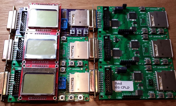
I’ve since built two more of the rev 1.1 boards. One worked fine, but the other showed the same pattern of occasional random write errors. Of the six rev 1.1 boards I’ve built, that means I only have three working boards. Arghh! 50% yield is not good. The random write error is maddening. It doesn’t happen very often, so it’s necessary to do a LOT of testing before I can be confident a particular board does or doesn’t have this problem. I spent a long time with a lens, an oscilloscope, and a debugger trying to explain what’s going wrong, but failed. My best theories are:
Software Bug – Perhaps there’s a problem with the Floppy Emu software, like a timing bug or uninitialized variable, and tiny variations in boards or components cause the bug to appear or disappear. This was my first guess, but if true I would expect a continuous distribution of bugginess across boards, rather than two groups of “working” and “not working” boards. I tested the working boards heavily, and they really do work 100%. I also made many experimental software changes that I thought might cause the problem to appear or disappear, but there was no change in behavior. And to my knowledge none of the rev 1.0 boards have this problem, even though they use the same software.
Soldering Mistake – I may have created a bad solder joint somewhere, leading to flaky behavior. That’s possible, but it seems pretty unlikely I’d make the exact same soldering mistake twice in six boards. And I’ve visually inspected the problem boards carefully with a 10x magnifier, and touched up all the likely problem points with an iron, without any success.
CPLD Damage – Some of the CPLDs might have been damaged by the firmware bug that shorted PWM to GND, resulting in buggy behavior even after the firmware was fixed. That’s certainly possible, but then why weren’t all the CPLDs damaged? Why just two of them? If this is the true explanation, then future rev 1.1 boards should all work OK now that the firmware bug is fixed.
Atmega1284 vs Atmega1284P Variation – Maybe some minor difference between the two types of the AVR microcontroller is causing unexpected problems. As far as I know, the only difference is that the “P” version uses Atmel’s Pico-Power system to enable very low power sleep modes. Since I’m not using those sleep modes, that difference shouldn’t matter.
Board Design Flaw – The rev 1.1 board could contain a design mistake not present in the original board, like substantial coupling between neighboring traces, signal reflections, or other noise that leads to intermittent problems. While the layout changes between rev 1.0 and 1.1 were minor, I can’t rule this possibility out.
Manufacturing Flaw – The rev 1.1 boards from Smart Prototyping might not be built to the same tolerances as the original boards from Dorkbot PDX. In terms of published specs like minimum trace width and spacing, the Smart Prototyping process should be fine, and I used their design rules file to verify my board in Eagle. I know other people have been successful with rev 1.0 boards not made by Dorkbot PDX, though I don’t think any have used Smart Prototyping specifically.
Unfortunately I’m at one of those points where I really don’t know where to go next. I could build a few more boards to test the CPLD damage theory. Or get some more Atmega1284P’s and build a few boards with those, or experiment with going back to the original PCB manufacturer or the rev 1.0 board design. But each of those experiments would require more time and money to test the theory. I’d need to see at least five good boards and zero bad ones before I had any confidence that I’d solved the problem. Spread across all the possible problem causes, I could end up building several dozen test boards, and still come up empty-handed if the true cause is a software bug or something else I haven’t considered.
Read 11 comments and join the conversationNew Floppy Emu Boards and Supply Noise
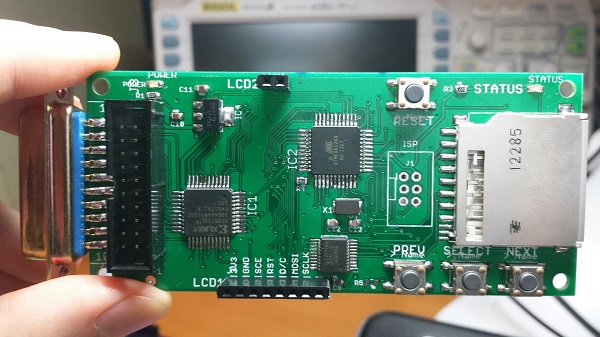
I finally got the new Floppy Emu revision 1.1 boards! Rev 1.1 has a few minor tweaks to prepare for selling assembled hardware. I built four of them with a soldering mini-marathon, and three of them work. The fourth I think I toasted somehow, but I’ll check it in more detail later. 75% yield isn’t so good. 🙂
Unfortunately something isn’t quite right. With the new boards I’ve built so far, I’m seeing anywhere from 3X to 10X more noise on the 5V and 3.3V supply lines, and I think this is causing random resets and spurious interrupts and other phantom problems. The noise is very regular, with a frequency of between 80 kHz and 130 kHz on both supplies. I was able to bring the supply noise under control by soldering an extra 10uF capacitor between the 3.3V and GND pins on the LCD, but it shouldn’t need one, since there’s already a 10uF cap between 3.3V and GND on the main board. Yet the difference with and without the extra cap is like night and day:
Rev 1.1:
new LCD (with extra 10 uF cap) and SD card: 80 mV noise on 5V supply, 100 mV on 3.3V supply
new LCD and no SD: 60 mV on 5V, 50 mV 3.3V
old LCD and SD card #1: 380 mv on 5V, 100 mV on 3.3V
old LCD and SD card #2: 840 mv on 5V, 280 mV on 3.3V
old LCD and no SD: 900 mv on 5V, 340 mV on 3.3V
Rev 1.0:
new LCD and SD card: 100 mV on 5V, 120 mV 3.3V
new LCD and no SD: 80 mV on 5V, 120 mV 3.3V,
old LCD and SD card: 100 mV on 5V, 120 mV 3.3V
old LCD and no SD: 80 mV on 5V, 100 mV 3.3V
I guess I could just go with the extra capacitor on all new boards, and call it done, but I’d really like to understand what’s going on. Quite a few things changed between revisions, any of which could affect supply noise:
- New board design relocated some parts and re-routed some traces
- Boards were manufactured by a different fab
- Using an ATMEGA1284 instead of ATMEGA1284P
- Different brand of 3.3V regulator
I’m tempted to blame the 3.3V regulator, but I don’t quite see how it could be at fault. The old regulator from rev1.0 and the new regulator from rev1.1 are virtually identical.
I’m going to do some more experiments before deciding how to proceed. If you’ve got any ideas on what to check, please leave a note in the comments!
Read 12 comments and join the conversation
What Is The Bus Pirate?
I’ve been aware of the Bus Pirate for several years, but never had a clear understanding of precisely what it is, beyond being a serial adapter of some sort. Its name suggests a black-hat hacking tool, or maybe something for defeating DRM locks. The official home page only says “The Bus Pirate is an open source hacker multi-tool that talks to electronic stuff”, but that one sentence explanation doesn’t help very much. Links to the Bus Pirate Manual just show an advertisement, and the few “Bus Pirate for Dummies” style of guides I found weren’t super helpful either. I finally got curious enough that I decided to just buy one, and get the sense of the Bus Pirate through hands-on experimentation.
My conclusion is: it’s great! Imagine every hardware programmer, debugger, serial cable, and interface tool you’ve ever used, rolled into one. That’s the Bus Pirate. But it’s even better than that, because the Bus Pirate also offers interactive diagnostic features those other tools never dreamed of. If you like to tinker with digital electronics, the Bus Pirate is the tool you’ve always needed, without realizing how much you needed it. Here’s some of what it can do:
- program or read an AVR microcontroller (replaces the AVRISP mkII)
- program or query CPLDs, FPGAs, ARM micros, and other JTAG devices (replaces tools like Altera’s USB Blaster)
- connect to serial devices over a USB to serial connection (replaces the FTDI USB-to-serial cable)
- read or write Flash and EEPROM memory chips
- communicate with virtually any SPI- or I2C-based chip through an interactive command line console or a binary API
- passively sniff the SPI or I2C bus while other chips are using it, and record traffic
- other goodies like a low-speed logic analyzer and oscilloscope mode, raw digital (bitbang) mode, and more
To be fair, the Bus Pirate probably isn’t the best tool for any of these purposes – it won’t replace your high-end logic analyzer or expensive JTAG debugger – but it offers an amazing breadth of functions in a single device.
History
The Bus Pirate was originally developed in 2008 by Ian Lesnet for Hack a Day, and his post introducing the Bus Pirate remains the best overall summary of what it is and what it does. Ian later founded Dangerous Prototypes and took the Bus Pirate with him, releasing the design into the public domain, but continuing to improve the hardware and software with the help of others. Making it public helped build a robust community around the Bus Pirate, and today there are several companies selling variants of the Bus Pirate hardware, including Seeed Studios and Sparkfun.
Unfortunately, the public nature of the design has led to fracturing of the hardware, and some neglect of the software and documentation. For example, Dangerous Prototypes and Sparkfun use different naming conventions when describing versions of the hardware, leading to confusion when reading that a particular feature is available in version 3.5. And depending on whose Bus Pirate and cables you buy, the mapping of wire colors to signals may be backwards relative to other hardware versions. Be careful if you’re using somebody else’s color-coded wiring diagram! To confuse things further, there are also two major versions of the hardware in simultaneous development: 3.x and 4.x. The 4.x version is supposed to be the “new” Bus Pirate, but despite having been released in 2010 it’s still officially beta hardware, and new users are encouraged to buy the 3.x version. In practice, the community seems about evenly split between 3.x and 4.x hardware users.
The software and documentation suffer from not having a clear owner or maintainer. Those things take a lot of work, so it’s not surprising that a public domain project has some hiccups there, but it does make things difficult for a new Bus Pirate owner trying to get oriented. There are tons of Bus Pirate wiki pages on the Dangerous Prototypes web site, but many of them are out of date or inaccurate, or duplicates of other pages, or contradict other documentation on the site. The software harbors a few more potential points of confusion, with different sets of files contained in each firmware archive, and much ambiguity about which firmware is the right one to use.
But ultimately these are just minor bumps in the road. It may take a bit of extra reading and experimentation to get everything configured, but once the Bus Pirate is set up, it’s definitely worth the trip.
Hands On
I bought the Seeed Studio version of the Bus Pirate, hardware revision 3.x, along with the female-to-female jumper cable. Other people seem to prefer the cable with grabber probes. Consider what you’ll be connecting to most often, and buy accordingly. Or get both cables – they’re cheap. I also purchased the optional clear acrylic case. Shipping from Seeed took about two weeks to the United States.
Nokia 5110 LCD
After connecting the Bus Pirate to my PC, and installing the recommended terminal software (TerraTerm Pro), I connected to COM4 at 115200 bps and was on my way! The interactive terminal was a little daunting at first. The basic idea is to use simple text commands to choose an interface mode like SPI, I2C, or UART, configure the options for speed, pull-ups, and such, then type in data values to be sent to the device. Any incoming data from the device is displayed in the terminal window as well.
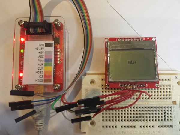
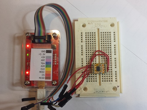
After plowing through a tutorial, my first test was interfacing with a Nokia 5110 graphical LCD. This 84 x 48 LCD has an SPI interface, and I’ve used it on several past projects. The Bus Pirate can optionally supply 3.3V or 5.0V to the connected device, so I turned on the power supplies and connected 3.3V to the LCD. The LCD’s SPI pins were connected to the corresponding pins on the Bus Pirate, and its D/C (data or command) pin was connected to the the Bus Pirate’s AUX pin. Finally, I tied the LCD’s reset pin to 3.3V.
From past experience with this LCD, I knew the magic series of command bytes necessary to initialize the display. In Bus Pirate terminal mode, they translated to:
a[0x21 0xBF 0x14 0x20 0x0c]
   a - set the AUX pin low (puts LCD in command mode)
   [ - asserts LCD chip select
   0xNN - data bytes to send
   ] - deasserts LCD chip select, ending the transfer
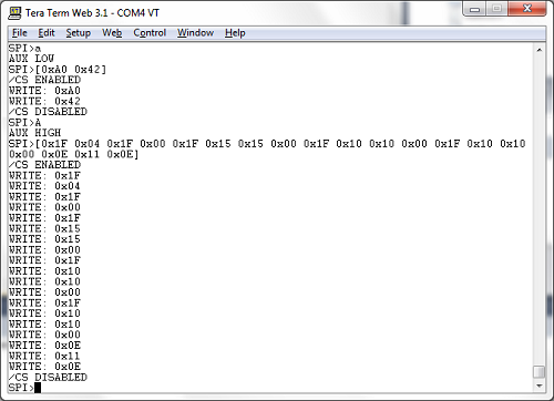
It worked! After a little more fiddling around, I was able to clear the display, set the cursor position, and print the “hello” message you see in the leader photo. In this case, my experimentation merely confirmed what I already knew about the LCD’s communication interface, but if I’d never used the LCD before, the Bus Pirate could have been a life-saver. Human-speed interactive communication with an unknown device like this is a much easier way of learning its behavior, compared to writing code for a microcontroller, or building a protoype PCB.
ADXL345 Accelerometer
My second test was an accelerometer module that I bought a few years ago, then put in a drawer and never used. Unlike the LCD, I had no prior experience with this chip. The ADXL345 can operate in either SPI or I2C mode, so for the sake of variety I chose I2C. Unlike SPI, I2C devices have a unique address used for bus communications, sort of like an Ethernet MAC address. Two addresses are needed: one for writing and one for reading. I could have read the datasheet to learn what addresses are used by the ADXL345, but I’ve got a Bus Pirate! So I connected up the pins, ran the Bus Pirate’s I2C address search macro, and voila! 0xA6 write address, 0xA7 read address.
OK, to go further I did need to peek at the datasheet. I learned that internal register 0 is the product ID register, and should return the value 0xE5. To read an I2C register using the interactive terminal, the syntax is not especially intuitive. To read the product ID register the command was:
[0xA6 0x00 [0xA7 r]
You’re probably thinking something’s wrong with those mismatched brackets, but it’s correct as written. [ sends an I2C start bit. 0xA6 0x00 identify the chip address and register number. [ sends another start bit, which is a restart, and is necessary for switching the chip from write to read mode. 0xA7 is the chip read address, and r reads a byte from register 0. Finally ] sends an I2C stop bit and ends the transfer. I ran the command, and saw happy 0xE5 come back as the read result.
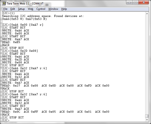
Reading the datasheet a bit further, I found that the accelerometer XYZ axis data is in registers 0x32 – 0x37. It’s two bytes per axis, with the low byte first. See the screenshot for the data from my test. The first time I queried the registers, the module was lying flat on my desk, with gravity nearly aligned with the chip’s Z axis. The measured axis values were 0x0027, 0x000D, 0x00FD. For the second test, I stood the module on its edge, with gravity nearly aligned with the chip’s X axis. This time the measured values were 0xFF0C, 0x0005, 0x0001. Pretty neat!
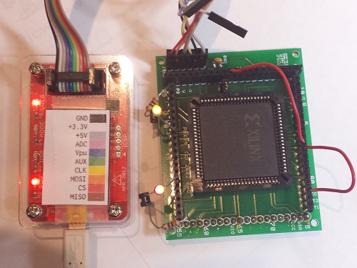
XC9572 CPLD
For my final test, I decided to try some JTAG programming. There are three different ways to use JTAG with the Bus Pirate, so it’s easy to get confused. The first method is from an interactive terminal session similar to the SPI and I2C examples. This isn’t very useful in practice, and support for it has been removed in recent firmwares, but it’s still mentioned in the documentation. The second method is to use the Bus Pirate as a JTAG dongle with OpenOCD software. I didn’t try this, but apparently recent versions of OpenOCD have Bus Pirate support built in, but it only works if you’re running the right firmware. I used the third method: using the Bus Pirate as a stand-alone XSVF player. XSVF files are a type of pre-recorded JTAG sequence, created by the Altera and Xilinx development tools for programming FPGAs and CPLDs.
Here’s where things get a bit complicated. My first two tests were interactive terminal sessions, running Terra Term on my PC with the default firmware 5.10 installed on the Bus Pirate. The XSVF player isn’t an interactive terminal mode, though, but a binary-only API requiring different firmware for the Bus Pirate. That meant I needed to learn how to update the Bus Pirate’s firmware and replace it with something different.
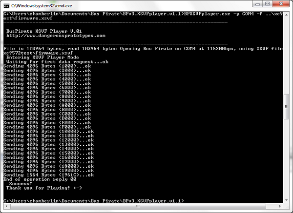
Poking around on the Dangerous Prototypes site, I found links to various firmware tools and downloads, but no indication of which one I should use. My Bus Pirate shipped with firmware 5.10, which seems to be the standard, even though it’s quite old and the latest firmware is 6.3. I eventually found what I was looking for, hidden inside the firmware 6.2 download archive: a firmware image named bpv3-xsvf-vb.hex, which provides the XSVF player functionality on the Bus Pirate. But how do you talk to the Bus Pirate when it’s in XSVF player mode, and send it the XSVF file you want to play? This requires a Windows program that’s inexplicably not included with the corresponding firmware, but must be downloaded separately. One I grabbed that as well, I was finally able to get started.
I’ve had an old XC9572 gathering dust in my parts box for years, and I’ve never actually used it, because I don’t own anything that can program it. Or I didn’t until now! I used the Xilinx ISE to create a simple design for the XC9572 – just a couple of AND and OR gates to prove that it worked. I then exported this as an XSVF file, connected the Bus Pirate, ran the XSVF player, and I was in business. It wasn’t fast, taking about 30 seconds for JTAG programming what must be the simplest part in Xilnx’s entire product lineup, but it worked. I hooked up some LEDs and jumper wires to exercise my AND and OR gates and make sure everything was working as expected. Hooray, new life breathed into this old CPLD!
Conclusion
The Bus Pirate is a remarkable tool. It’s a shame that the hardware, software, and docs have become somewhat muddied and difficult to follow, but it’s worth the effort to dig through and get it working. If you’ve got a box full of single-purpose programmer/adapter devices, then this is for you. I expect the Bus Pirate will occupy the top spot in my electronics toolbox for a long time to come.
Read 3 comments and join the conversation
Getting Ready to Sell

I’m almost ready to start selling Floppy Emu hardware! My plan is to offer two options: a fully assembled and tested unit, and a “DIY kit” containing the PCB board, LCD, and DB-19 connector. These are the hardest parts to find, and the ones where shipping costs kill you if buying individual quantities, so the DIY kit should be helpful for people making their own builds. The assembled units will be hand-built and tested by me, and I’m a little scared about signing myself up for that much labor. If there’s enough demand I’ll look into having an electronics assembly shop do the work, but I expect large quantities are necessary for that to be economical. I haven’t decided on prices yet, but it’ll be low enough that people find it a good value, while still high enough to make it worth my time and effort.
Meanwhile, feature development continues. I’ve completed a revision 1.1 board, which has a number of small changes:
- LCD backlight
- mounting holes (can build a case for the board)
- support for the lock tab on the SD card
- removed the motor LED, since motor status is now displayed on the LCD
- removed the unused JTAG connector footprint
- repositioned the buttons and status LED
- added a test point for oscilloscope probing
- probably some other things I forgot
I also added support for Disk Copy 4.2 disk images, long filename support, and subdirectories on the SD card (see photo). Things were getting a little out of hand once there were more than a few dozen disk images on the SD card, and the subdirectories really help. This makes OS installs almost enjoyable! Just download the disk images from Apple, copy them to your SD card, boot the Mac from the Install Disk 1 image, and off you go.
The last major piece of the puzzle is 1.4 MB write support. I’ve got this partly working already, and writes of individual sectors and small files are OK, but writing a larger file to a 1.4 MB emulated floppy causes things to go haywire. The lack of any real debugging tools (other than printing to the screen) makes this a pain to troubleshoot, but I think I’m pretty close to resolving it.
Read 8 comments and join the conversation1.4 MB High Density Floppy Emulation
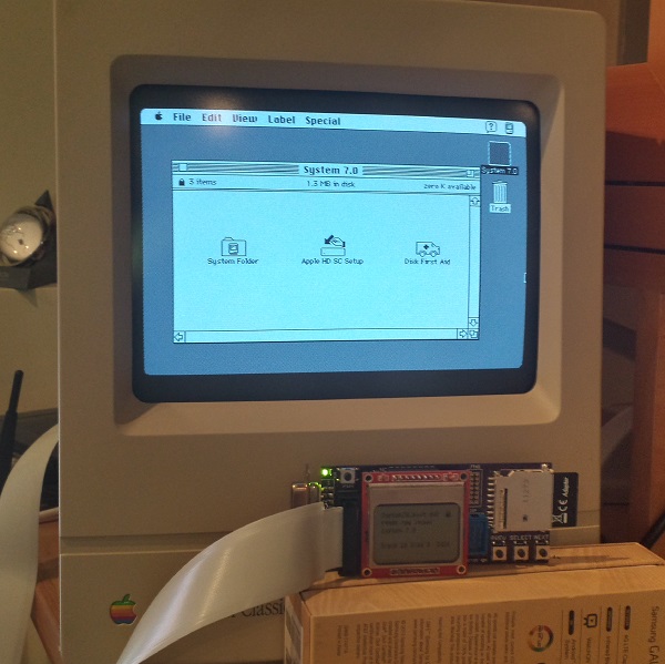
WOOOOO! Floppy Emu’s last big goal has been reached, and 1.4 MB disk emulation is now working! The photo shows a Mac Classic, booted into System 7.0 from a 1.4 MB high-density disk image. Combined with other recent improvements, this means Floppy Emu now works for 400K, 800K, or 1440K disk images in raw .dsk or DiskCopy 4.2 .image format, on any Mac from the 128K to the Mac II series and beyond.
1.4 MB disk support proved to be very similar to 400K/800K support in concept, but completely different in details. Data on 400K/800K disks is stored using a technique called GCR, which dates all the way back to the Apple II. GCR defines how data is encoded as flux transitions on a magnetic disk (or an emulated version of one, like we have here). In contrast, 1.4 MB disks store data using a technique called MFM, which is used by PCs as well as other classic systems including the Amiga and Atari ST. While GCR and MFM serve the same purpose, they are quite different, so Floppy Emu’s microcontroller and CPLD software both had to be extensively modified to add MFM support. For the curious, this Atari ST page has an outstanding explanation of floppy data encoding and MFM, almost all of which is relevant to the Macintosh too.
Aside from the MFM encoding change, another big challenge was maintaining MFM’s higher data rate. A Macintosh 400K or 800K floppy sends bits to the floppy controller at 500 kHz, but a 1.4 MB floppy sends bits at 1 MHz! That means Floppy Emu’s AVR microcontroller and companion CPLD needed to work twice as fast as before to serve data to the Mac, or else an underrun error would occur. My first attempts resulted in something that was almost but not quite fast enough, leading to a maddening situation where data transfers seemed to work much of the time, but would flake out with seemingly random errors before an entire sector could be transferred. In the end I had to review the C compiler’s assembly output, and do some cycle counting by hand, in order to optimize the code to the point where it was fast enough to consistently meet the data rate demands.
Beyond the MFM differences, high density Mac disks also use a different signature than 800K disks for tagging sector address and data blocks, and use a different checksum algorithm. 800K disks use a near-incomprehsible checksumming algorithm that was probably invented by Woz himself, while HD disks use a standard CCITT-CRC16 algorithm. Then just for laughs, high density disks also use a 1-based numbering scheme for sectors, instead of 0-based. That little twist took me quite a while to recognize!
The last hurdle was related to the larger size of a high-density floppy track, and I still don’t have a perfect solution for it. For 800K disks, the number of combined sectors on both sides of a track is variable, but is never more than 24. With 512 byte sectors that’s 12K of data – small enough to fit into the microcontroller’s 16K of RAM with some room to spare. But for high-density disks, there are 36 sectors and 18K of data – it won’t fit! Instead of buffering an entire track in RAM, then, I had to fall back to the technique I originally used for 800K disks, and do SD card transfers on the fly at the instant the data is needed. It works well enough when reading the disk image, but when writing it’s very sensitive to the speed and variability of the SD card transfers.
There are still many little bugs to fix and things to polish, and a few other features I’d like to add, but with the addition of 1.4 MB support I think Floppy Emu is effectively finished. Or if not finished, at least worthy of a “1.0” version number release. My next plans are to polish up the code and documentation, squash a few more bugs, and then build some Floppy Emu units for those who want one. Happy hacking!
Read 5 comments and join the conversation
Fixing 30 Year Old Apple ROM Bugs
After nearly a year of inactivity, I’ve started work on Floppy Emu again! One of my first priorities was compatibility with Macs that have a 400K floppy drive – the original Mac 128K, and the Mac 512K (not the 512Ke). Floppy Emu emulates a 400K/800K external floppy drive, and it works fine with 400K disk images, so I originally assumed it would have no problems on those old 400K-based machines. Wrong! Reports trickled in of mysterious Sad Mac errors and other problems when using Floppy Emu with those oldest Mac models. After ignoring the problem for months, I finally got ahold of a Mac 512K so I could investigate things firsthand.
Some brief experimentation showed that Floppy Emu was at least partly working with the 512K. When I “inserted” a disk image of a non-bootable disk, the Mac rejected it and showed the X’d disk icon. But when I inserted a bootable 400K system disk image, the Mac chewed away for a moment, then died with a Sad Mac error code 0F0004. So it was clear the Mac 512K could recognize the difference between a bootable and a non-bootable disk, but was failing to actually boot when using Floppy Emu. The same disk image and Emu hardware booted fine on a Mac plus, so the problem looked like an unknown incompatibility between the Mac 512K and Floppy Emu.

The Sad Mac – such a cute way for a computer to die. Much friendlier than a blue screen of death, but just as fatal.
From past experience, I knew the Mac 128K and 512K used a different version of the Apple ROM than found in the 512Ke and Mac Plus. The 512Ke/Plus ROM added support for 800K floppy drives. But as long as only 400K disk images are used, I couldn’t see any reason Floppy Emu shouldn’t work on 128K/512K Macs with the old ROMs. After all, how would the Mac even know that Floppy Emu wasn’t a 400K drive? The real 400K and 800K drives are virtually identical, with the same connector, same internal registers, etc. The only difference is that one is a single-sided drive and one is double-sided. Also the Mac directly controls the speed of a 400K drive with a PWM signal, but an 800K drive ignores the PWM signal and self-regulates its speed.
I hunted the internet for details on 30-year-old boot errors, and found two explanations for error 0F0004. One said “Voltage too Low, adjust voltage to +5.0v.” and another said “Division by Zero”. How could there be two such radically different meanings for the same error? But things started to fall in place after I found this Apple Tech Note, which said that 0F0004 was a result of using an 800K external disk drive on the Mac 128K/512K with the old ROMs. So somehow the Mac was still identifying Floppy Emu as an 800K disk drive, which caused it to die. But how did it know?
ROM Diving
When all else fails, it’s time to look at the source code. In this case that meant disassembling the ROM from the 128K/512K to find out what the floppy driver is doing. I’ve done this a few times before now, but it’s still a major pain. Even with a 68K disassembly tool, and substituting symbolic names for all the Mac memory-mapped hardware, it’s still an opaque mess of assembly language code that doesn’t yield its secrets easily. It’s hard enough just to locate the relevant floppy routines, let alone understand the fine details of how they work. But after a day of poking and prodding, I found some code that looked very suspicious:
P_Sony_MakeSpdTbl:
1E82   285F                  Move.L    (A7)+, A4
1E84   343C 0080             Move      $80, D2		; set PWM value to $80
1E88   615C                  Bsr       P50		; measure TACH speed, get speed1 result in D4
1E8A   6B56                  BMI       L309
1E8C   2604                  Move.L    D4, D3		; copy result to D3
1E8E   343C 0100             Move      $100, D2		; set PWM value to $100
1E92   6152                  Bsr       P50		; measure TACH speed, get speed2 result in D4
1E94   6B4C                  BMI       L309
1E96   2A04                  Move.L    D4, D5		; copy result to D5
1E98   9A83                  Sub.L     D3, D5		; D5 = difference between speed1 and speed2
1E9A   E38B                  LsL.L     $1, D3
1E9C   7C04                  MoveQ.L   $4, D6
1E9E   4BFA FFC8             Lea.L     DT19, A5
1EA2   6100 FCA2             Bsr       Sony_SetupSonyVars
1EA6   47F1 101A             Lea.L     $1A(A1,D1.W), A3
1EAA   7400       L304:      MoveQ.L   $0, D2
1EAC   341D                  Move      (A5)+, D2
1EAE   2E02                  Move.L    D2, D7
1EB0   D45D                  Add       (A5)+, D2
1EB2   E24A                  LsR       $1, D2
1EB4   D484       L305:      Add.L     D4, D2
1EB6   9483                  Sub.L     D3, D2
1EB8   6A02                  BPL       L306
1EBA   7400                  MoveQ.L   $0, D2
1EBC   EF8A       L306:      LsL.L     $7, D2
1EBE   6702                  BEQ       L307
1EC0   84C5                  DivU      D5, D2		; divide D2 by (speed2 - speed1)
Comments were written by me, after analyzing the code. This particular routine does some kind of calibration of the floppy drive – it varies the PWM signal, then measures the resulting drive speed as indicated by a value called TACH. I think it’s trying to establish a linear relationship between PWM and TACH, since that relationship may vary slightly between real 400K drives. There’s a lot going on in this routine, and I’ve truncated it to only show the first 25 instructions. But notice it contains a DivU instruction? There aren’t many places that division is used in the original Mac ROM, so that’s significant.
Looking deeper, the routine makes two drive speed measurements, then does some math to compute a value in D2, then finally divides D2 by the difference between the two speed measurements. But what happens if the two speed measurements were equal? Division by zero! Hello, 30 year old ROM bug.
On a 400K drive that’s controlled by the Mac’s PWM signal, the speed measurements will always have different results, because the PWM is different during each measurement. But on an 800K drive which self-regulates its speed, and on Floppy Emu which has a totally fake speed, the PWM changes will have no effect. That means both speed measurements will get the same result, and the Mac will crash with a division by zero error when it calls this ROM routine. Getting two different speed measurements was probably a safe assumption in 1983/1984 when the code was written, but it still would have been nice to do some defensive programming and add a zero check there, to handle the case of a broken drive or broken assumptions.
Fixing It
Once I understood the cause of the 0F0004 error, the question was how to modify Floppy Emu to avoid it. The TACH speed signal that Floppy Emu generates is obviously fake, since there are no moving parts. It calculates how fast the drive motor should be spinning, given which track is being accessed, and creates a series of pulses on TACH at the appropriate rate. To avoid the division by zero crash, the TACH rate needs to vary, so that two successive measurements see different TACH speeds.
One solution would be to use the PWM signal from the Mac, since that’s its purpose. By analyzing the PWM duty cycle, the Floppy Emu hardware could infer how fast the Mac wanted the drive to spin, and generate an appropriate TACH to match. Unfortunately, the hardware doesn’t even have the PWM pin connected. And if it did, it’s not certain that it could do the necessary duty cycle and TACH calculations fast enough, or efficiently enough to fit in the remaining logic space.
My solution was to constantly flutter the drive speed TACH signal. The flutter rate must be fast enough that two successive measurements will see different rates, but not so fast that two successive measurements will span the entire flutter cycle and so see the same rate. The flutter amplitude must be large enough for the speed measurements to be different, but not so large that the measured speed falls outside the valid range for the current track being accessed. With a little experimenting, I settled on a flutter cycle period of 640 ms and a flutter amplitude of about 0.25%.
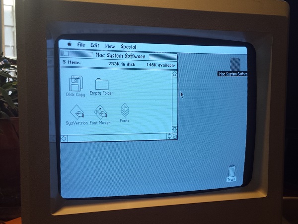
And it works! The image above shows the Mac 512K running System 0.97, Finder 1.0, booted from Floppy Emu. Those fonts sure are weird.
A Bit of History
When Macintosh external 800K floppy drives first became available, in 1985/1986, owners of the Mac 128K and 512K faced the same problem I did here, only they couldn’t modify the drive’s TACH behavior to work around the ROM bug. Instead, Apple released a system patch called HD20 which fixed the bug and added 800K drive support. But using it was a pain: you had to boot from a 400K floppy in the internal drive first, which contained the HD20 patch, and then you could mount an 800K floppy in the external drive. Booting from an 800K drive wasn’t possible. It wasn’t a very nice solution.
If that ROM routine’s author had added a zero check, this wouldn’t have been necessary. Mac 128K/512K owners could have booted directly from an 800K floppy in the external drive, loading the HD20 init in the process. Everything would have been great. Instead, that divide by zero bug doomed them all to a miserable 800K experience.
When Apple and Sony were developing the 800K external drive, they must have known this was a problem, and they could have used the solution I did to flutter the TACH speed. In 1985 they couldn’t just drop a 25-cent microcontroller into the drive to synthesize TACH, but they could have added a simple RC circuit to inject some AC “noise” into the TACH signal at the appropriate amplitude and period, achieving the same result. Everything would have been great. But they didn’t, and all those 128K/512K owners were forced to endure the 400K floppy boot-swap dance forever.
Read 5 comments and join the conversation