

The Quest For A Simple Level Converter
Sometimes the simplest things give me the most trouble. I’ve been working on a downloader cable adapter for the Backwoods Logger, with the goal of supporting both 5V and 3.3V FTDI cables. Because the Backwoods Logger is a 3.3V design, the incoming TXD (transmit data) signal from a 5V cable needs to be lowered to 3.3V for safe operation. However, the incoming TXD signal from a 3.3V cable should be passed through unmodified. Outgoing signals from the Logger require no conversion, because a 3.3V output is still a valid logic “high” for a 5V system. I need a level converter for a single input, that operates correctly with both 5V and 3.3V inputs with no configuration or jumper settings.
Level Converter Chip
One solution is to use a 3.3V chip with 5V tolerant inputs, like a 74LVC244. That would work, but I’d prefer something simpler and smaller if possible, since I only have a single input to convert.
Clamp Diode
A second solution is to use a series resistor and a clamp diode, like this (image from daycounter.com):
![]()
That prevents the voltage at the 3.3V Backwoods Logger input from going more than a diode drop above the 3.3V supply. With a standard silicon diode’s drop of 0.6V, that clamps the voltage to 3.9V. For the ATmega328, that’s not safe: its maximum rated voltage on any input is just 0.5V about VCC. A germanium diode has a drop of 0.2 to 0.3V, so that would work, but it’s not a part that many people typically have handy in their parts bin.
This solution also has the drawbacks of consuming current from the 5V output, and dumping current into the 3.3V supply, raising the supply voltage. The FTDI outputs have a maximum output current of 24 mA. Assuming a germanium diode with a 0.2V drop, that means R1 needs to be at least 62.5 Ohms. Frankly I’m not sure how to quantify the risk of dumping current into the power supply. In the case of the Logger Classic with its tiny CR2032 battery, dumping 24 mA into the battery in the wrong direction definitely doesn’t sound good.
Zener Diode
The approach that appealed to me most was to use a series resistor and a Zener diode connected to ground, like this (image from daycounter.com):
![]()
The Zener has a known reverse-bias breakdown voltage called the Zener voltage. Raise the voltage above the Zener voltage, and the diode conducts. The series resistor produces a voltage drop, so that the voltage at the Backwoods Logger input never rises above the Zener voltage. You can get 3.0V or 3.3V Zeners (or lots of other values too).
So I ran out and bought some Zeners, and built this circuit, and it didn’t work at all how I’d expected it to. I used a 3.0V Zener, and a 100 Ohm series resistor, to limit the current drawn from the FTDI cable to 20 mA. When I connected a 5V dummy output, I got 2.91V at the Logger input. That seemed odd, it was off by 0.09V, but it was still close enough. Then I connected a 2.95V dummy input (the actual voltage from my crummy “3.3V” breadboard regulator), and I got 2.4V at the Logger input. Huh? That’s not going to work. I had expected that for any voltage below 3.0V the Zener would do nothing, and for anything above 3.0V it would clamp it to 3.0V, but that’s clearly not what happened.
What went wrong? Truthfully, I’m not exactly sure. The datasheets talk about a minimum current necessary to get the Zener effect, but I’m not sure that applies here. I can’t safely increase the current further anyway without damaging the FTDI cable. But would more current even solve this problem? It makes sense that the Zener wouldn’t really turn on instantaneously at 3.0V, but rather would begin to conduct more and more as the voltage approaches 3.0V. With a voltage of 2.95V, the Zener would already be partly conducting, pulling the voltage seen at the Logger input below 2.95V. But how much below? How can this be quantified?
One thing in particular bugs me about all the Zener diode datasheets: every datasheet lists values for standard measurements called Izt, Rzt, Izk, Rzk, Rz, and a few others. These are standard measures from some hypothetical standard Zener graph, but the datasheets never actually show this graph, and I’ve never been able to find one anywhere. I know “k” is for “knee” and I believe “t” is for “test”, but what I really need is an actual IV curve for a Zener with these values labeled. Then I think I’d understand this better.
Further Complications
Just to make things more interesting, there’s one more constraint to consider. The Logger Classic uses an unregulated battery as its supply. It can work just fine at battery voltages of 2.8V, and probably down to 2.5V or even lower. In order to stay within the VCC + 0.5V margin of the ATmega328P, the input voltage must not go more than half a volt above the potentially fading battery voltage. A standard 3.3V input when the battery is 2.7V would actually damage the ATmega. That’s why I chose to use a 3.0V Zener rather than a 3.3V one. That should be safe down to a battery voltage of 2.5V, below which I could configure the ATmega’s brownout detector to engage.
The Way Forward
I’m going to sleep on this, and see if anything brilliant comes to me. If anyone else has a suggestion, please reply in the comments. Assuming I can’t find a way to make the Zener work while still meeting the other constraints, then I’ll probably cave in and use a level converter chip. Without really understanding the implications of current flowing into the supply battery under the clamp diode method, I wouldn’t feel comfortable relying on that approach.
Read 19 comments and join the conversationMac Floppy Emulator Revisited
A few weeks ago, I posted some thoughts on an SD-card based floppy emulator for classic Macintosh computers. This idea has been on my mind again recently, and I’m trying to determine whether this could be done solely with a microcontroller and a few other support chips, or whether a CPLD or FPGA is needed. I also took a look at a few related designs for inspiration. If a working emulator could be built entirely from a microcontroller and other common parts in through-hole packages, then it could be built by anyone on a piece of perfboard or even a breadboard. In contrast, a CPLD or FPGA would require a custom-made circuit board, and probably voltage level shifters as well. Unfortunately, it looks like a lone microcontroller probably wouldn’t be sufficient.
Need for Speed
The fundamental problem is access speed. The Mac reads and writes the disk drive control registers like they were an external memory: there are 4 register select lines (one doubles as the write data line), a read data line, and a write enable. Reviewing the floppy driver ROM routines, there are typically only 3-4 CPU instructions between when the last register select line is set correctly, and when the data is read or written. Call it 3 instructions to be on the safe side: that’s 12 clocks of the 68000 CPU. If the microcontroller can’t respond that fast, it won’t work. For example, say the Mac wants to test whether the drive head is at track zero. It sets the register select lines to select the TK0 register, and 12 clock cycles later it reads the result from the drive. If the microcontroller can’t respond to the change on the register select lines fast enough to put the correct value on the read line before the Mac reads it, then an incorrect value will be read. For writes, the write enable signal LSTRB may be asserted for as little as 12 clocks. If the microcontroller doesn’t check the the signal at least that often, then a write may be missed.
I wrote some AVR code to do basic read/write management of the drive control registers, and looked at the compiled output. The read loop is 16 AVR instructions long, and something like 20 AVR clocks (I didn’t count exactly). If the AVR is clocked at the same 8 MHz speed as the Mac, then that’s not enough time. If it’s clocked at the max AVR speed of 20 MHz, then it might be fast enough. However, this assumes the read loop begins at the same instant that the CPU changes the register select lines. If instead the lines change just after the AVR reads them, then it will spend 15 clock cycles producing the result for the old register, and 16 more cycles producing the result for the new register. So in practice, the AVR needs to be fast enough process its read loop twice within the register-select-to-read-data time of the Mac.
Maybe with better optimized code, or an overclocked AVR, or a PIC or Propeller or another high-speed microcontroller, it might be fast enough to act as a set of emulated drive control registers. But it would be sitting in a busy loop constantly watching the register select lines, providing zero additional time to read/write the SD card, or poll for user input buttons, or refresh a status LCD. Using interrupts to watch the register select lines would only make things worse, since then you’d have the interrupt latency on top of the 16 AVR instructions of processing to produce a result. I don’t really see how this approach could work.
HxC Floppy Emulator
The HxC Floppy Emulator project uses a PIC and an SD card to emulate a floppy drive, and works on many classic computers like the Amiga and Atari ST, but not the Macintosh. So how does it do it? Unfortunately as far as I can tell, it’s a closed design and the schematics and PIC firmware source aren’t available. I’ve posted a question in the forums to confirm. I think I can guess why it works, though. Unlike the Mac, those other computers use a parallel control interface for the floppy drive. In other words, all the control lines (step direction, step request, side to read, write data, etc.) and state lines (track 0 indicator, read data, write protect, etc.) are broken out with individual wires. That’s a lot easier to implement with a microcontroller, and there’s no need to constantly watch the register select lines and race to put the right value on the data line before the Mac reads it.
Now What?
I still won’t rule out the micrcontroller-only approach entirely, but it would definitely require a high-speed microcontroller, carefully-crafted loops for speed, and cycle counting to generate the output data and motor speed tachometer signal with exactly the correct timings. That doesn’t sound like much fun. I keep thinking that I must be overlooking something, and maybe there still is a way to do this easily with just a microcontroller, but so far I’m not seeing it.
If a lone microcontroller won’t work, what about a microcontroller with a few support chips? For example, the mcu could output the contents of all 16 control registers simultaneously on separate pins, and the register select lines connected to a 16-to-1 mux to select the desired register without any mcu intervention. Or the registers could be implemented in an external register file or latch of some kind. I think this approach could work, but would end up with half a dozen or more low-density 7400 series and similar chips. And at that point, I think it would be better to replace them all with a single CPLD.
That brings me to where I think this is all going: an emulator consisting of a CPLD and a microcontroller working in tandem. That’s not the worst design, but it’s not great if the goal is to design an emulator that anyone can build. A CPLD-based design would require a custom PCB, JTAG programming hardware, and other headaches. That’s not a problem for me, but I was hoping to design something usable by a wider audience who would probably balk at those requirements.
Read 8 comments and join the conversationHalloween LED Display Demo
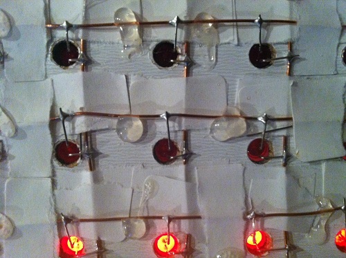
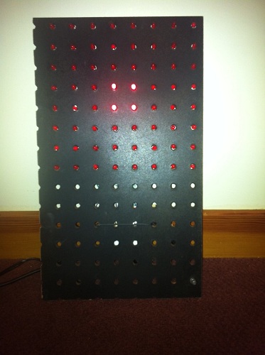
I’ve been working with my daughter Alice on an LED lightboard project for Halloween, and today we finished the construction. Whew! We started out two weeks ago with a giant 4 foot x 2 foot pegboard from Home Depot, and ambitious plans to make various Halloween shapes by populating specific holes. Reality quickly sunk in, though, as we realized how much work it would take to do something interesting with a 1152 hole pegboard. We eventually settled on building a much smaller 8 x 8 fully-populated LED matrix instead, controlled through software to make a variety of patterns and designs.
Even this 8 x 8 matrix was a lot of work, and for anyone contemplating a similar project, I’d recommend just buying a prebuilt LED display matrix like the Peggy 2LE instead. We probably could have found a simpler way to build the matrix, but it was a fun project nonetheless, and the result looks great. Take a look at the video, and then I’ll explain how it’s built.
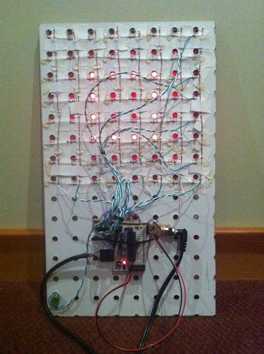
We started with a pegboard with 1-inch hole spacing, painted black on the front display side. Alice cut lengths of bare copper wire for the column busses, and lay them on the back of the board, just to the right of the holes. The bus wires were temporarily fixed in place using torn strips of adhesive tape. She then laid more bare wire on top to form the row busses, with additional layers of tape at the crossing points to ensure the row and column wires didn’t touch. The tape didn’t stick very well, so she reinforced the grid with hot glue, taking care not to cover the points where LEDs would be soldered later.
The next job was mine: building the controller circuitry. I used a MAX7219 LED driver, which is a nice (but expensive) single chip solution for controlling up to 64 LEDs. It handles all the multiplexing and storage of pixel values, so the microcontroller doesn’t have to do anything expect send SPI commands to change values when desired. The 7219 rapidly scans through the columns at about 800 Hz, activating each one in turn. This is fast enough that human vision sees them as being all active at once. The chip has sixteen driver pins: one for each row and column. It pulls one column high while the others float, and pulls rows low if the LED at that row/column intersection should be lit.
The 7219 can supply 320 mA to a column, which when divided by eight rows provides 40 mA per LED when the column is activated. Because the scanning action results in a 1:8 duty cycle for the columns, the average current per LED is only 5 mA. Typical current for an LED is about 15 mA, so 5 mA is fairly low. I was worried the display would look pretty dim as a result, but as you can see in the video, it’s actually quite bright.
I built the 7219 circuit on a piece of perfboard, hand-placing all the connections between the chip, row/column headers, control header, and power. What a mess! Whenever I build something on perfboard, no matter how simple, it always seems to turn into a giant mess with flakey connections everywhere. Unfortunately this example was no different. Soldering in the components is no problem, but I can never get the wires to stay put when soldering the connections. Any connection involving more than two wires is also a hassle. My pain with perfboards is why I favor manufacturing custom PCBs even for simple projects, but in this case there wasn’t enough time before Halloween.
With the control circuit ready, the final construction step was to populate the board with 64 LEDs. Alice and I took turns soldering and bending LED legs to shape. It was her first big soldering project, and she had a blast. It helped that everything had wide open joints to solder, and a mistake couldn’t do anything worse than kill a 10 cent LED. Populating the whole board took about two hours, working slowly and carefully through each joint.
The finished board worked– sort of. It worked as long as you never lit more than 5 LEDs in a column, otherwise the display would go dark until you reset the Arduino. I wasn’t expecting this, but with my geek dad pride on the line, I had to find a solution.
My first thought was that this was some kind of clock glitch problem. I guessed that my terrible wiring combined with the sudden voltage swing from 6+ LEDs turning on was glitching the SPI clock. I spent some time fiddling with the clock wire and other control lines in an attempt to clean things up, to no avail. I also realized that a glitchly clock would likely produce display errors, but not make the screen go permanently dark, so I started looking for another explanation.
The display was finally fixed by reducing the current draw (and resulting brightness). The 7219 uses a current set resistor between two pins to control the current to the LEDs. I initially followed the sample circuit in the datasheet, using a 10K ohm resistor to provide maximum brightness. Through trial and error, I found that I had to increase the resistance to 30K before the display worked reliably. This should have resulted in a 3x reduction in current to the LEDs, but I only noticed a very minor reduction in perceived brightness.
Why was it necessary to use a larger set resistor? One possibility is that it was somehow drawing more than 320 mA with the original resistor, causing the 7219 to overheat or trip some kind of internal protection circuit. I can’t think what I might have done to make it draw too much current, though. A more likely explanation is that my shoddy power and ground wiring has a non-trivial amount of resistance, so when the current draw is high enough, +5V is pulled down and ground is pulled up far enough that either the Arduino or the 7219 no longer function. Either way, reducing the current fixes the problem, but one is a thermal problem and one is a supply voltage problem. I’ll leave further investigation for another holiday.
Now we need some cool animation displays for this board! Alice has been learning the basics of programming at Codecademy, and has already done some simple button-pushing and LED-blinking Arduino projects, so with a little help from me I think we can create a great-looking Halloween display.
Read 7 comments and join the conversationBackwoods Logger – Open Source and On Sale
The Backwoods Logger is a programmable graphing altimeter / thermometer, developed and documented here at Big Mess o’ Wires. Today is a big day for the Logger: I’m re-launching it as a formal open hardware project, and also offering a small test run of pre-assembled Backwoods Logger Mini units for sale. After corresponding with many enthusiastic people over the past months, I’m convinced there’s a community of Logger-heads out there that’s bigger than just me. My goal is to bring together people who are merely curious about the Backwoods Logger, or are interested in buying a prebuilt Logger, or have already built their own Logger, or are interested in making improvements to the existing Logger software and hardware.
Re-launching the Backwoods Logger as an open hardware project means it will no longer be a personal endeavor developed solely by me, but a collobarative effort that welcomes involvment from everyone. The project is hosted at Google Code: check out the new Backwoods Logger project page. All the source code, schematics, and other design files are there. And if you’re interested, please consider joining the project.
I’ve also created a Backwoods Logger discussion mailing list, intended for questions, ideas, or any other conversation about the Logger. The list is public and is hosted by Google Groups, and you can join or leave the list at any time via the group settings page. Membership in the discussion list is separate from membership in the Google Code project, and everyone’s welcome to join the mailing list regardless of whether they’re project developers or just curious about what’s happening in Logger Land.
Backwoods Logger Mini Sale
![]()

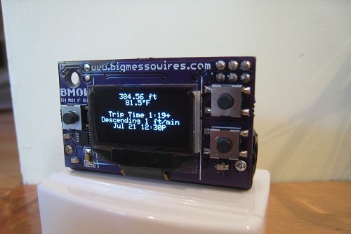
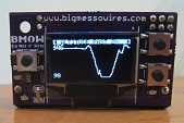
To help kick things off, I’ll be selling a small test run of pre-assembled Backwoods Logger Mini units. The Mini is the OLED version of the Logger, pictured above.
- Temperature measurements in 0.5 degree steps, from -10F to 117.5F
- Air pressure measurements in 0.01 in-Hg steps, from 5.9 to 36.12 in-Hg
- Altitude (calculated from air pressure) measurements in 2 ft steps, from -1384 ft to 14999 ft
- Can configure metric Loggers with units in degrees C, millibars, and meters on request (ask when ordering)
- Graphs of temperature, pressure, and altitude over time
- Three graph time scales: past 2 hours, past 10 hours, past 2.5 days
- Current rate of ascent/descent
- Estimated time of arrival at a user-defined altitude
- Weather forecast
- Station pressure and pressure at sea level
- Snapshot feature – make a permanent record of date, time, altitude, temperature, and pressure at important waypoints
- Current date and time display
- Battery voltage indicator
- Sound on/off control
- 128 x 64 OLED screen
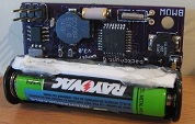
- Battery Life: 3 – 5 months with a single AAA battery
- Dimensions: 1.9 x 1.1 x 0.7 inches (48 x 28 x 17 mm)
- Weight: 0.7 ounces (19g), including battery
Also check out this Backwoods Logger demo video to see a demonstration of the Logger’s features. The video shows a Logger Classic, which has a lower-resolution screen and is slightly bigger and heavier than the Mini, but otherwise has an identical set of features. Don’t see a feature you want? Join the project, and help create it.
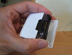
The hole in the corner of the Mini board can be used to tie it to your backpack, or wear it around your neck on a lanyard. The Mini has no case, so if you expect wet weather you’ll need to provide your own. The last photo above shows a Mini inside a dental floss container!
The price for this test run will probably be about $59, but will depend on how many confirmed orders I receive beforehand. You should understand these will be prototype units, and may contain bugs or other defects, but I’ll do my utmost to resolve any problems that might occur. If you’re interested in purchasing a Backwoods Logger Mini, please contact me and let me know. I expect the lead time to be about six weeks.
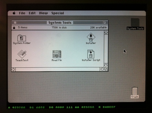
Read 9 comments and join the conversationA Working Hardware Replica of the Mac Plus

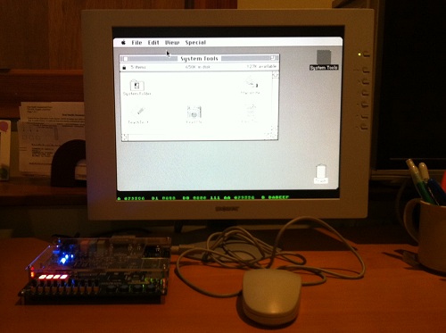
Plus Too is a home-made replica of a classic Macintosh computer using an FPGA. The project reached a major milestone yesterday, booting to the Finder for the first time, and running several programs. Since then I’ve been getting many inquiries, and because not everyone’s been following the project since its beginning, I’ve created a Plus Too project summary page to document the progress so far and my plans for the next version. If you’re new to Plus Too, please begin by reading the project summary page.
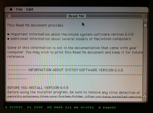
The screenshot above shows a Mac Write document opened with Plus Too. Because there’s no keyboard support yet, the document was created on another computer and added to the Plus Too boot disk image. Below the Macintosh screen region, hardware debugging information is displayed in green. This debug overlay is possible because a pixel-doubled 512 x 342 Mac image conveniently leaves some extra vertical space on a 1024 x 768 VGA display. From left to right, the debugging information shows the current state of the CPU address bus, data bus in, data bus out, address strobes, previous address, and breakpoint address. A poor-man’s breakpoint system is implemented by setting a breakpoint address with panel switches. When the address bus matches the breakpoint address, the CPU’s memory transfer acknowledge signal is withheld, effectively pausing the CPU.
The current system is implemented entirely with an unmodified Altera DE1 FPGA development board. The next version will use a custom-designed circuit board instead of the DE1 kit. The revised Plus Too will use a real 68000 CPU, and will add a microcontroller to manage the floppy disk SD card interface. It will also add the physical connectors necessary to use a real Mac Plus mouse and keyboard if desired.
What Works
The current system recreates a computer similar to a Mac 512Ke, with 512K of RAM and no SCSI. It boots from a System 6.0.8 floppy disk image stored in ROM. The disk image is pre-encoded into a series of virtual tracks and sectors, with the proper low-level layout, header, footer, checksum, and GCR disk byte format. This encoding is performed offline, using a custom-made utility program. Applications can be launched from the disk and run normally.
What Doesn’t Work
The disk is read-only, and there’s no keyboard, sound, SCSI, serial ports, real-time clock, or parameter RAM. The planned SD card interface for loading disk images hasn’t yet been built. There are some obvious stability problems, and the system tends to freeze up if the mouse is moved too rapidly. Disk I/O seems strangely slow– slower even than on a real Mac 512Ke or Mac Plus. There’s a long, long way to go before this project could be considered “done”, but it’s an exciting start!
Read 4 comments and join the conversationPlus Too – Hello World!
Plus Too works! Holy cow, it really works. Hot damn!

I didn’t want to tackle SD card loading yet, so the GCR-pre-encoded 800K disk image resides in ROM, just above the Macintosh ROM image. The floppy drive module uses the video module’s memory access time slot during hblank periods to load disk data, transparently to the CPU.
Plus Too ran for about five minutes while I took these photos, then it locked up. Not bad for the first boot.
Now, to celebrate with a cold beer!
Read 6 comments and join the conversation