

Logger Mini Refinements
![]()
I’ve made some refinements to the Backcountry Logger firmware, based on my experiences in the field last weekend. I’ve decided to bring the Logger Mini with me on my upcoming John Muir Trail trip, rather than the Logger Classic that I brought to Mount Langley. The Mini (shown here) is smaller, lighter, and has a higher-resolution screen than the Classic. Earlier I was concerned about the durability of the Mini, but I constructed a fairly rugged carrying case for it out of a dental floss container!
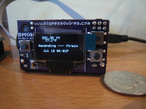
The biggest problem I had on the Langley trip was accidental button pushing while the logger was in my pocket. The first photo shows my solution to this problem: both the PREVIOUS and NEXT buttons (but not SELECT) must be held in order to unlock the device when awakened from sleep mode. I also got fancy and threw the BMOW logo onto the unlock screen for fun. So far this approach to unlocking seems to have conquered the random button pushing problem nicely.
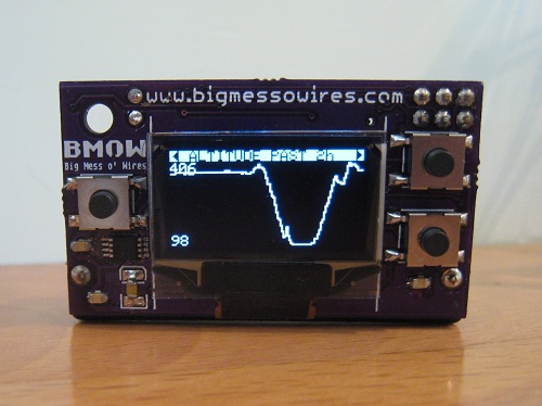
The extra resolution of the Mini’s 128 x 64 displays really helps the graphs — they look much cleaner than with the Classic. I boosted the OLED display brightness to the maximum, but unfortunately it still looks washed-out when viewed in direct sunlight.
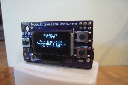
The Mini has a SQ-SEN-200 omnidirectional tilt/vibration sensor, which the firmware uses to detect movement. If there’s movement for four consecutive minutes, it concludes you’ve begun a trip, and starts the trip timer. After 6 consecutive minutes with no movement, the trip timer stops. In practice the movement detection with the SQ-SEN-200 works very well, but the time thresholds may need to be tweaked. The 1:19 trip shown here was my walk down the hill to the store and back.
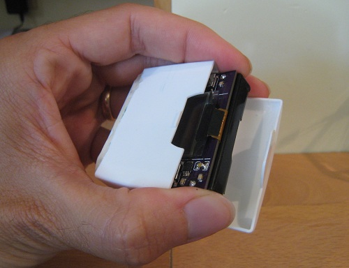
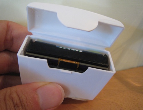
To protect the Mini, I built a storage case out of an old dental floss container. I cut off the lower half of the container to reduce its height, and then hot-glued a plastic scrap over the bottom opening to seal it. The resulting case is very sturdy, and fits the Mini perfectly.
The firmware now almost completely fills both the program and data memories on the ATmega, which I think is my clue that development is done. Save for possible bug-fixes, then, any further Backcountry Logger development will focus on hardware improvements such as different displays or batteries, and simplifications and cost-reductions of the circuitry.
Read 2 comments and join the conversationBackcountry Logger at Mt. Langley
The backcountry logger and I climbed Mt. Langley this past weekend, providing its first real test in the wild. Langley is a 14026 foot peak in the southern Sierra Nevada mountains of California, about five miles from Mt. Whitney. I brought both the classic logger and the new mini logger for the trip, but ultimately left the mini logger in the car due to concerns over its fragility. The classic logger worked very well, and accompanied me through all the miles of trail and rocks to the summit.
The drive from my home in San Francisco to the trailhead near Lone Pine passes right through Yosemite National Park, so I was able to test both loggers in the car. As we traveled through Tioga Pass on the highway, I was thrilled to see cool elevation profile graphs with numbers in thousands of feet– my first direct proof that the logger works at elevations beyond spitting distance from sea level. You could clearly see each smaller pass on the graph as a series of humps on the overall upward trend. I don’t know why seeing a real-time elevation profile of your travel is so awesome, but it is.
During the drive, I found that the mini logger’s OLED screen didn’t hold up as well in sunlight as I’d hoped. While it looks beautiful indoors, outside in the sun it has a decidedly washed-out look. It’s still readable, but the basic LCD of the classic logger is much better for reading in the sun. I think the OLED offers some brightness or contrast configuration options that may help a bit, so I’ll research those.
We arrived at the 10000 ft trailhead, where I left the mini logger safely in the glovebox. Upon returning two days later, it showed some cool graphs of the 65-degree day to night temperature swings in the car. Meanwhile I packed the classic logger in my backpack’s waist pouch, and my hiking buddy and I hit the trail. Despite being in high mountain country with near 360-degree views, the GPS failed to get a satellite lock, so we relied on the logger’s elevation info plus the topo map to measure our progress on the trail. Spotty or non-existent GPS reception plagued us all weekend, so we were very happy to have the logger to help measure progress during our climb.
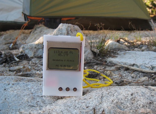
The first night we made camp a bit over 11000 ft, and rose early the next morning for summit day. My immediate thought was to check the overnight temperature graph, which showed a nice curve with an overnight low of 30.5 F around 1:00 AM. Ice in my water bottle confirmed the sub-freezing temperature. By 6:52 when this picture was taken, the sun was up and it had already warmed into the mid 40’s. After more experimentation that day and the next, I found that the temperature readings are easily skewed by sunlight or human hands. When left sitting in the shade or dark, the logger traces a nice smooth temperature graph. But move into a patch of sunlight, and the temperature reading can easily jump 10 degrees or more in couple minutes. Just holding the logger in your hands and pressing its buttons can have a similar effect. To get a good temperature reading, it’s necessary to leave the logger on the ground in the shade for a few minutes, then press a button once to wake it and immediately read the temperature.
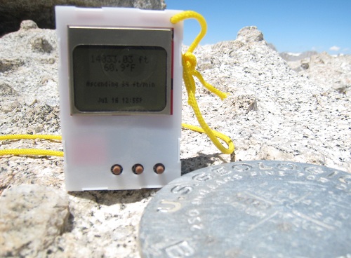
I had planned to calibrate the logger’s altitude reading every time we came to a pass or peak whose altitude could be determined from the topo map. In practice, though, this wasn’t possible. The real trail wasn’t always quite where the map showed it, and often it wasn’t clear exactly where the trail was at all. Above about 11500 ft, the route to the summit was more of a network of faint use trails converging and diverging, rather than a single well-defined path. Only when we reached the summit was I able to calibrate the logger, where I found it was off by about 300 feet.

This isn’t a mountaineering web site, so I won’t say too much about the ascent, other than that it was a lot tougher than I’d expected. We climbed New Army Pass, then hiked several miles across a desolate plateau at around 12000 ft, before reaching the foot of the summit block. Even in mid-July, there were still several snowfields that we had to traverse or detour around. At about 12500 ft, the trail faded away completely, and we were left with 1500 vertical feet of picking our way through refrigerator size boulders, trying to find a good route towards the top. I’m in pretty good physical shape, but the high altitude combined with the steepness of the slope reduced my pace to a crawl. I wore the logger on a lanyard around my neck, and checked it often to see how many more vertical feet remained.
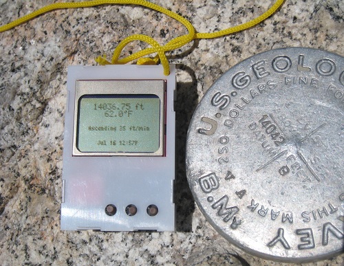
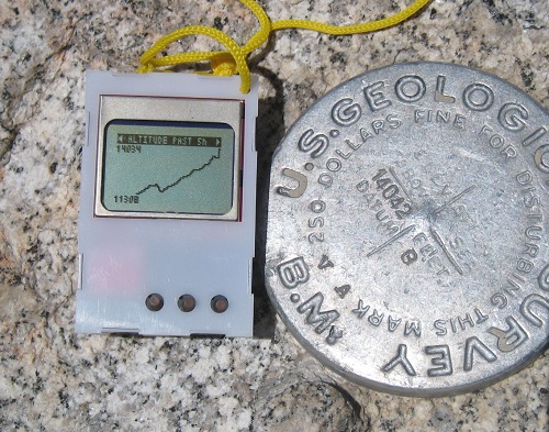
Here you can see a couple photos of the logger next to the USGS survey marker at Langley summit. The graph in the second photo shows how we had to descend several hundred feet after New Army Pass, before resuming the climb towards the summit. On the return trip to camp, that extra 300 feet of climbing on the way “down” made an exhausting day all that much harder.
Overall the logger worked well, and I was very happy to have it along. One need became obvious after a day of real use, however: some kind of “lock” state. I was constantly pushing buttons accidentally, especially when I wore the logger around my neck, giving rise to unexpected beeping noises. All the random button pushing normally left the logger on some random screen or menu when I went to use it again. While annoying, this was generally harmless, except on the last day when the logger locked up completely. I’m not 100% certain the lock-up was due to random button pushing and not some other failure, but I was unable to revive it without removing the battery to reset. I plan to make a software mod that requires the PREV and NEXT buttons to be pushed simultaneously, while SELECT is not pressed, in order to wake the logger from sleep.
This weekend I begin the John Muir Trail, a three week and 220 mile journey through the Sierras in terrain similar to Langley. The logger will be along for the trip!
Read 1 comment and join the conversationI am the Best Solderer in the World
Who’s the best solderer in the world? I am. That’s right. All you other soldering fools just want to taste my sweet victory because the Logger Mini works!
OK, in reality I may be in the bottom decile of the soldering class, but after assembling this bad boy, I’ll never fear soldering anything again. All surface mount parts, all crammed in way too densely, all impossible to debug when it doesn’t work… but it does work. Me and my big, bad soldering iron have tamed this beast. Most of the assembly wasn’t too bad, and I was able to get the majority of the parts soldered within a couple of hours. The fine-pitch ICs didn’t give me too much difficulty this time either. But as always, there were a few twists and turns along the way.
As I predicted in my last post, there were clearance problems between the battery holder and several components. I unwisely designed the battery to sit on top of a few smaller components, and it quickly became clear that wasn’t going to work. I cut away part of the holder’s body with a knife to make things fit, but the real solution will require a different style of holder or a slighly larger board. I also struggled with a missing component when I discovered I’d ordered a 390 Ohm SMD resistor instead of 390K Ohm. Rather than string 1000 resistors together in series, I cut up a 390K resistor pack I had on hand, bent the pins to size, and shoehorned it onto the SMD pads.
The BMP085 pressure/temperature sensor also gave me a nasty surprise. Its connection points are underneath the device, but for some reason I thought they also extended outward to the edges of the device and up the sides, providing access for the soldering iron. Nope. All the connection points are completely hidden underneath, inaccessible. Fortunately the pads on the PCB extend out about 1mm beyond the perimiter of the chip. What I ended up doing was tinning all 8 pads, then placing the BMP085 on its footprint, and reheating each of the tinned pads in turn while I pushed down on the chip from above. The idea was that the solder would transfer heat under the chip, melting the solder underneath and bonding it to the connection point sitting on top of it. It seemed to work.
The real challenge proved to be debugging. After finishing assembly, the screen remained stubbornly blank. With no idea if it was a software bug, circuit design error, soldering mistake, or defective part, and no good way to troubleshoot, I was pessimistic I’d ever fix it. This is the kind of situation where I can easily convince myself it’s hopeless and give up, but I tried to be methodical at exploring problem theories as much as possible. Eventually I tried touching an oscilloscope probe to each of the 30 pins on the display connector ribbon, to try to see what was going on, and I discovered that touching one particular pin caused the display to start working! After retouching that pin with the soldering iron, I was in business.
The Logger Mini worked fine for many hours, and I started work on the necessary software changes. Eventually, though, the BMP085 sensor stopped working. The sensor actually lies partly underneath the battery holder, making the problem especially difficult to troubleshoot. Again, I desparied of ever finding a resolution. After many false starts and much hair pulling, I desoldered the battery holder, which was less difficult than I’d feared. I powered the board with a pair of alligotor clips while I poked at the sensor. After retouching all the sensor’s pins with the iron, it sprang back to life. I then replaced the battery holder, restoring everything to factory new condition.
I made a few quick power measurements of the Mini, testing current draw straight from the battery. With the display on, the current is between about 8 to 15 mA, depending on how many pixels are illuminated. With the display off and the logger asleep, the current is 120 uA. That’s a higher sleep current than I was expecting, and some more investigation is needed to determine why. Still, with those current numbers I estimate the battery life will be a very respectable 4-5 months.
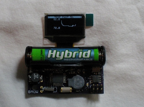
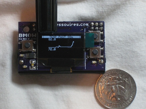
The photos here show a straight port of the software from the Logger Classic, and the graphs still only use the 84 x 48 resolution of the Classic. I need to do some more work to fit everything to the Mini’s 128 x 64 display, but development time is running out before the first of my Sierra hiking trips.
Read 4 comments and join the conversationGoodies in the Mail
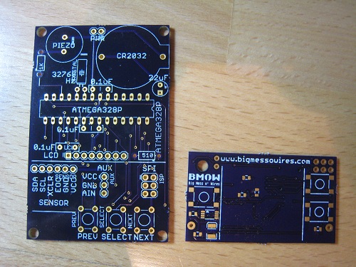
While I was traveling, a few goodies arrived in the mail. The most exciting of the bunch are the PCBs for the Backcountry Logger mini version. Pictured here is the mini PCB next to the classic, to give a sense of just how small the mini is. I’ll be assembling the mini prototype sometime in the next few days. Beyond simply being smaller, it also has a few new features, and a completely different battery and power system. Hopefully it works! I think there are going to be some clearance problems around the battery, since I’d thought the battery holder was a pair of end clips, rather than the full-length holder that it is.
![]()
Also in this week’s mailbag was the snap-together case for the classic logger. This case was designed using vector drawing software, and the six sides were intended to snap together using beveled tabs on the egde of each piece. It’s a tricky design, because the depth and bevel angle of the tabs must be just right, or else the pieces will be too loose to stay together, or too tight to snap at all. When sizing the pieces, things are complicated further by the need to account for the kerf, which is the thickness of the laser cut. Even when it works as intended, this type of design looks a bit ragged, since the tabs prevent having smooth corners.
I had the case manufactured out of 0.8 mm thick white Derlin by Ponoko. This was my first time using Ponoko, and while the price and quality were good, the speed of the service was pretty slow. It was nine calendar days between when I uploaded the design and when it was acutally cut and shipped. For a simple one-sheet design using in-stock material, I was expecting it to be cut the next business day. My only other laser-cutting experience was with Pololu, which does laser-cutting as a sideline to their main business, and my order from them was cut next day. For a business like Ponoko whose entire premise is custom-cut parts, a nine day lead time seems a bit high. I probably just need to learn to be patient.
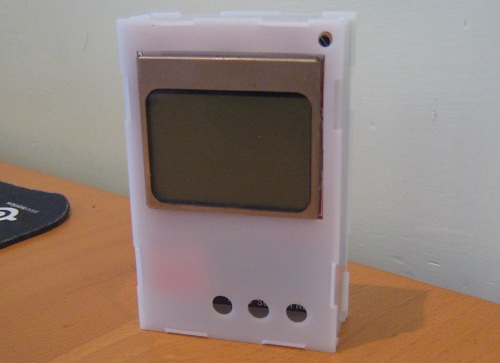
As received, the tabs on the case pieces were substantially too big, and the pieces wouldn’t snap together even by applying extreme force. Whether this was because the true kerf was less than advertised, or because my design was flawed, I’m not sure. After half an hour with an exacto knife, I was able to whittle down the tabs and assemble the case you see here. It’s pretty nice, except… where are the buttons? DOH! I guess I should have used tactile switches with a longer plunger, so they’d extend far enough to exit the case. Back to Digikey to order some.
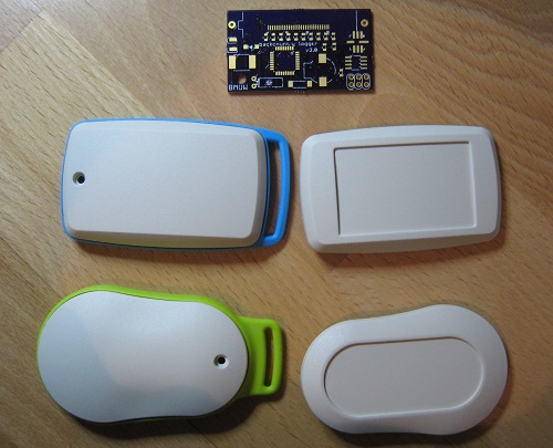
The last mail delivery was some enclosure samples from OKW. These are the enclosures Cesar recommended in an earlier comment, and OKW was kind enough to send me free samples. They look great! I really like the look of the pear-shaped one with green trim, but I think it might be a bit too small to hold the logger mini.
Be the first to comment!Backcountry Business
Since a few people asked, I’ve posted the source code for the Backcountry Logger. In a first for me, the source is offered with a specific license. In this case, it’s the Creative Commons BY-NC-SA 3.0 license. I feel a bit silly discussing licenses here, but I see some possibility for the Backcountry Logger to turn into a bit more than just a personal project, and I’m attempting to protect that possibility. I’m happy to have people learn from the code, offer suggestions for improvements, and use it in their own hobby projects, but I’d hate to see it taken wholesale and turned into part of a commercial product.
The next step for me (once I’ve received the necessary parts) is to build a v3 logger prototype, which I’m calling the mini logger. The mini logger is the 2 x 1 inch version using an OLED display and a single AAA battery. In constrast, the classic logger that was demoed here earlier is 2.75 x 1.75 inches, and uses an LCD display and CR2032 watch battery. While reviewing the mini logger’s design yesterday to create the bill of materials, I realized that it’s really not all that much smaller than the classic logger. And the mini is actually just as thick as the classic, if not thicker, due to its AAA battery. It seems likely there will be further prototypes after the mini, attempting to get a good balance of size and features. I’ve been thinking about a version more like the classic, with the LCD and CR2032, but with all SMD parts and the mini’s extra EEPROM. That would require finding a primary source for the raw Nokia 5110 LCD, instead of buying it on a breakout board from Sparkfun.
Once I’ve got a few prototypes built, I hope to get them in the hands of some outdoorsy people who can put them to use, and offer feedback. What looks great on the bench may not work very well in the field, so real-world testing will be essential.
This is a device that should appeal to any outdoorsy people interested in examining altitude, temperature, or pressure movements over timescales from an hour to two weeks. That includes hikers, climbers, skiers, trail runners, cyclists, kayakers, snowmobilers, horseback riders, and probably many others. You can get similar information from your GPS or altimeter watch, but few of those offer detailed graph views, and GPS’s don’t have the battery life needed for long trips in the wild. An app for a GPS-equipped smartphone might work, but toting your smartphone on your adventure isn’t ideal. The closest similar devices are probably the Garmin Foretrex 401, Garmin eTrex Summit (discontinued), or Suunto Core.
I’m also thinking this project needs a better name than “Backcountry Logger”. Nobody wants something called a “logger”– that’s either a guy who cuts trees, or a tool for making boring lists. “Backcountry” is an awkward word as well. Besides being a mouthfull, it also sounds like it excludes potential uses in the civilized world like skiing or urban adventures. A good name is also probably a short name. Maybe something like “Sportview” or “Outdoor Tracker”. Bah, I’m no good at names!
Read 5 comments and join the conversationTiny CPU Update
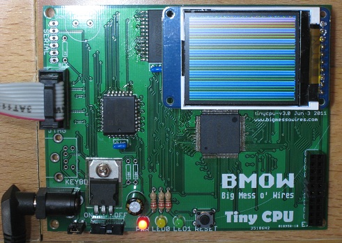
Slow progress continues on the assembly and first boot-up of Tiny CPU. The photo shows a sample program written in Tiny CPU assembly language, drawing a color pattern on the LCD. The serial port and keyboard interface haven’t yet been added to the board, but the Max II CPLD, SRAM, and Flash ROM are all working fine from both an electrical and a design standpoint. After the initial round of swearing at the soldering iron, there were no further electrical problems at all, so all the work has been on configuration and software. The goal of designing a novel CPU architecture and implementing it in hardware has been met successfully.
Of course it’s not all roses and sunshine, and several smaller problems plus one big one have slowed progress and cast doubt on future direction. Debugging has been a major challenge. When things don’t work as expected, or do nothing at all, there aren’t many good tools to help diagnose the problem. The best tool I’ve found thus far is TopJTAG Probe, a $100 software program that lets you examine the current state of any pin, and display continuously-updating state data in a waveform-style window. It’s great for examining external signals at the pins, but the internal machine state remains invisible. It’s also limited to about 400 samples per second due to its use of JTAG boundary scan, which requires slowing the CPU clock to around 100 Hz to do any debugging. My free trial expires in 17 more days, and I’m undecided whether I’ll purchase it.
Altera also offers system debugging tools, including a scriptable Tcl console, in-system sources and probes, and a virtual JTAG interface. Not surprisingly, these tools all require on-chip logic resources, and Tiny CPU has few LE’s to spare. The most promising tool looks like their Signal Tap II logic analyzer, but it requires on-chip RAM, and the Max II has none. Altera doesn’t appear to offer any tools that work purely through JTAG boundary scan without any on-chip logic resources, like TopJTAG Probe. I thought the jtag_debug interface of the scriptable Tcl console might be what I was looking for, but I was unable to get it to work.
When the CPU is running, it’s pretty slow. It took four seconds to fill the LCD with the color test pattern shown in the photo. Much of that is due to the inefficiency of the bit-banged SPI code I wrote to communicate with the LCD, but the 2.6 MHz clock speed is also a factor. The 2.6 MHz is provided by the Max II’s on-chip oscillator, whose frequency is fixed. It can be divided down using logic if a slower clock is needed, but it’s not possible to go faster than 2.6 MHz. According to the timing analysis report, the CPU should run at up to 40 MHz.
Design Disaster
The biggest problem by far is the bank-switching design. Tiny CPU has a 10-bit address space, enabling 1K to be addressed directly. The companion module Tiny Device performs bank switching, mapping 128 possible 512-byte banks of RAM and ROM into the lower and upper halves of the CPU’s address space. When I first described Tiny CPU’s bank switching design, it seemed a clever and elegant way to expand the address space. After working with it in real programs, however, it feels like a complete disaster. It’s confusing and cumbersome. It complicates the design of the programs, the assembler, and Tiny Device. It makes simple things hard. In short, it needs to be taken out back and shot.
Jumping between routines in different banks requires locating the code such that the first instruction of the routine in the target bank is at the next consecutive address, modulo 512, after the instruction in the source bank that alters the bank register. In this way, execution “falls through” to the target bank, transparently to the CPU, by altering the bank register. In practice I’ve found it very difficult to line up the addresses of entry and exit points in different banks. There’s probably some way to abstract it into a general jump table in each bank, but I haven’t found it yet. Adding a new “far call” CPU instruction might help, but I’m very reluctant to embed knowledge of the bank register in the CPU itself, since at the moment it’s just a memory-mapped port handled by Tiny Device.
Given time, the bank-swapping procedure may seem more intuitive and less onerous, but I’m skeptical. And unfortunately 1K is small enough that programs need to deal with bank swapping a lot. It’s even more common than it seems at first, since the upper half of the CPU address space is always mapped to a fixed block of RAM, so programs running from ROM really only have 512 bytes of space to work with before they need to worry about swapping.
Ideally I’d like to increase the address space to something larger, but that would force major changes all over. The 16-bit instruction encoding uses 6 bits for opcode and 10 bits for address, so a larger address space would mean larger instructions. The assembler would need to be substantially altered. And of course the Verilog source for Tiny CPU and Tiny Device would need major alterations as well. My enthusiasm for such a large refactoring right now is pretty low.
Maybe the best use of Tiny CPU is as a small soft-core to incorporate into larger FPGA designs, where a simple microprocessor is needed and the 1K address space limit is not a problem. It would offer an even smaller alternative to soft-cores like PicoBlaze, and be easily portable to any vendor’s FPGA hardware. In this scenario, Tiny CPU would be used alone without Tiny Device, and the RAM and ROM would likely be FPGA logic resources rather than actual external components.
I leave tomorrow for a 10-day trip, so I’ll think it over while I’m away and decide how to proceed with Tiny CPU development when I return.
Read 3 comments and join the conversation