

No-Connector AVR Programming
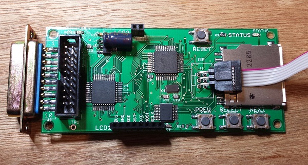
Here’s a handy trick I developed while searching for ways to reduce the cost and assembly time of Floppy Emu boards. The board has space for a 3 x 2 shrouded IDC header, where the AVR ISP cable should connect. But that connection is only needed once, the first time the AVR is programmed – all future software updates are loaded from the SD card using the bootloader. So why waste 75 cents and 30 seconds of soldering on a part that’s only ever going to be used once? It’s a small saving, I admit, but those savings add up.
OK, the programmer cable has a 3 x 2 female connector, and the board has an unpopulated footprint of 3 x 2 holes. Now what? My first attempt at a “no connector” solution was a straight 3 x 2 male header plugged into the cable connector, with the other end placed loosely inside the board footprint’s holes without soldering. By itself the fit was too loose, and the pins didn’t make reliable contact with the insides of the holes. If I pushed and twisted the connector with my finger, though, I could usually get all six pins to make contact long enough to successfully program the AVR. But as this only gave me one free hand, and didn’t work 100% reliably anyway, I gave up on that technique.
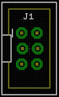
With board revision 1.1 I tried something new. Using Eagle, I created a staggered 3 x 2 header footprint, offsetting every other pin 5 thousandths of an inch from the centerline. I hoped this would help lock the pins tightly in place, keeping them pressed against the insides of the holes without solder and without my hand to brace it. But when the new boards came in, I was disappointed to find that while the staggered footprint was somewhat better than the original, it still didn’t work reliably. Sigh.
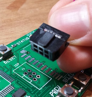
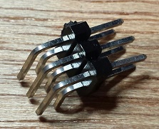
But every failure is just another step on the road to success! After more experiments, I finally hit upon a winning solution using a 3 x 2 right-angle header, with a small piece of scrap wedged under it for leverage. And I later found that the SD card holder is exactly the right size and in the right location to provide the necessary leverage, making for a quick and easy connection that’s 100% reliable with no soldering. I just plug one end of the 3 x 2 right-angle header into the programmer cable, and the other end into the holes in the board, with the connector and cable pressed against the top of the SD card holder. Once AVR programming is complete, I pull everything out and can re-use the parts for the next board. Hooray!
Read 20 comments and join the conversation20 Comments so far
Leave a reply. For customer support issues, please use the Customer Support link instead of writing comments.
You need one of these http://www.tag-connect.com
Interesting idea! For my AVR stuff, including my assembly of two Floppy Emus, I used a solderless header:
http://www.ebay.com/itm/10-Pin-Solderless-Header-SB5100-SB5101-Cable-Modems-Premod-/390722553214
The pins are thick enough that you can push down to make contact but don’t have to snap it in all the way. I just broke off part of it to turn it into a 6-pin header.
Yeah, either of those would probably be better for building high volumes of stuff. I was trying to find a solution that didn’t require any new parts. That Tag Connect appears to triple the required board area, though, with the holes needed for the clip. There’s also a version without a clip, but then I’m not clear what actually holds it onto the board. Doug, the solderless header looks like it might be difficult to pull out again once you’ve got it in. How tight is the fit?
I don’t actually snap the solderless header in all the way. If I did, you’re right, it would be a pain to remove and probably damage the plated through holes. But if I just press it against the through holes, it makes a good connection and pulls off easily when I’m done. It actually takes a ton of force to snap the header in place, so it’s basically impossible to accidentally push it in too far.
This is what pogo pins are for, no? You could even use a smaller footprint with those.
I used pogo pins to make jigs and even a 6 pin header for AVR programming to avoid the same issue you’re having. Post herer: http://lowpowerlab.com/blog/2013/06/27/illustrated-guide-to-making-simple-jigs-for-programming-and-testing/ and the pogo pin AVR cable: http://lowpowerlab.com/wp-content/uploads/2013/06/DSC_0851.jpg
Before that I just used a 2×3 straight pin that I used to hold at an agle in the programming header then use my other hand to do the few clicks necessary in AVR Studio … it worked.
I’m familiar with pogo pins, although I’ve never used them. But what holds the pogo pins in place? http://lowpowerlab.com/wp-content/uploads/2013/06/DSC_0851.jpg shows it held with your hand, which seems nearly as inconvenient as the first solution I tried with the 3 x 2 straight header. For higher volumes of production, I assume you’d build a jig or clip of some kind to hold everything together tightly without requiring a hand to steady it?
And Felix, you have an interesting blog! I’m always looking for more good tech blogs, so everyone’s welcome to promote their blog here in the comments. Chances are if you find BMOW interesting, I’ll find yours interesting too. Maybe I’ll do a post reviewing some other blogs sometime.
Use the force, Steve 🙂 .. use gravitation
You can put your device and these pogo pins upside-down like on this photo http://lowpowerlab.com/wp-content/uploads/2013/06/DSC_0911.jpg and let the gravitation do the job. To tighten all parts you can use some rubber band or anything heavier on the top of such “sandwich” to make more stress on contact area.
On the subscect of pogo pins, there’s this:
http://protofusion.org/wordpress/2013/05/open-hardware-pogo-pin-programmer/
I used the same unpopulated header trick for bulk assembly on my sensors: http://www.mike-stirling.com/2012/11/wireless-sensor-boards-arrived/
I find it works just as well as the Tag-Connect, which I am using on a product at work. Overall, Tag-Connect works out slightly smaller even with the holes though, because the pitch is finer.
Is it possible to preprogram chips before soldering? Although I’m not sure that would make physically connecting to the chip any easier.
i like your style… yeah looking closer at mine those through-holes are staggered… Awesome.
I’m thinking that it must be possible to create a reliable staggered land pattern for a straight 2×3 ISP header. Maybe instead of offsetting the two center holes towards one direction they should be offsetted against each other. Whatever is the case I plan to figure it out.
If you figure it out, let me know! Maybe the holes should be offset a little bit further, or the corner holes should be offset instead of the center ones. The solution I have now is fine for my needs, but it would still be interesting to find the ideal stagger pattern for future projects.
Sure, I’ll let you know. Time create some test boards!
Thinking more about this I concluded that we should probably separate the case of 1 row and 2 row headers. The existing alternating pins method looks fine for 1 row headers.
As for 2 row headers I’d rather bring all the columns of the two rows either closer or farther from each other by 5 mils consistently. This is the simplest approach there is (which is usually the best one) and given the even distance between the pair of pins it should result in a more reliable connection.
Of course I have yet to test this but this is my theory so far. Suggestions are welcome! 🙂
I recently have been looking into this too, and came across this page:
http://www.instructables.com/id/LED-Pocket-Watch/?ALLSTEPS
Specifically:
http://www.instructables.com/files/orig/FVS/HEUP/H9T4CLND/FVSHEUPH9T4CLND.png
This wacky zig-zag AVR connector guarantees friction with a header. I’m interested to try it!
Mad propos to you, Kaz! Why experimenting when this guy has already figured it out. Will use his pattern. Thanks!
I’m thinking that if I do it in my next batch of ISP boards, I might do the opposite (have the middle pins toward the outside). I think it could make the routing a little easier than having the inner pins recessed, but I guess I won’t know that until I try…
The other thing I was thinking was to move the pins slightly inward, saving those few mils on the outside too (in other words, why move all the pins in just the X or Y direction, when you can move them both and save a bit of board space too? People love teensy bits more board space!)