

Circuit Protection: Economics and Electronics
Remember this problem that I analyzed a year ago, with mysterious damage to the CPLD chip? I still haven’t found a permanent solution. It’s rare enough that it’s not much trouble to just repair or replace affected boards, but it’s annoying, and I’d sure like to fix it if I can. I’m not completely certain what causes it, nor how to fix it, but I have a theory I’m going with. The challenge is that the extra cost of parts and assembly to address the problem may actually be more than the cost of making occasional repairs, creating the awkward result that I would lose money by making things more robust.
This type of BMOW post often gets picked up by Hack-a-Day or Hacker News, spawning an off-site discussion thread about how stupid I am. Please be kind and understand that I’m not a professional, and if you think I’m doing it all wrong, I probably am! Leave your feedback in the comments below, and let me know how I could have done it better.
Economics
This is a low-volume hobby product, a disk drive emulator, and it’s designed and built by a single person in his spare time – me. In the past year, I estimate I’ve spent about $500 on hardware repairs and replacements for boards that had CPLD damage. That includes direct costs, as well as the cost of my time. $500 may sound like a lot, but I’ve sold about 300 boards during that time, so the amortized cost is only $1.67 per board. There’s also an intangible cost when a product fails and a customer has to return it – they get annoyed, my reputation suffers, and maybe I lose out on some future sales. That’s not good either. Including those intangibles, let’s say the total cost of this issue is an even $2.00 per board.
Assuming I knew exactly what the problem was and exactly what to change in order to fix it, implementing the change would need to cost less than $2.00 per board. Otherwise I would be spending more to prevent the problem than the damage it caused! It would be like buying Monopoly’s “Get out of Jail Free” card for $60, when getting out of jail normally only costs $50. And what if I wasn’t certain the proposed change would fix the problem? Then the cost of the change would have to be even less than $2.00, in order to compensate for this uncertainty. Maybe $1.50 or less, depending on how confident I was in the solution.
The reality is that implementing a change for less than $1.50 or $2.00 may not be easy. I suspect the problem is related to over-voltage on the 12 CPLD I/Os, and if I use a resistor or buffer on each input, it will require a minimum of 24 extra pins/pads on the board. The board assembly cost is around $0.05 per pin, so that’s already $1.20 right there, without even considering the cost of the parts themselves or any other extras. Add in the cost of the new parts, and adjust for any uncertainty in the solution, and the total costs might outweight the benefits. D’oh!
Electronics
If you haven’t already, check out last year’s post, especially the many excellent comments from readers. Based on that discussion, and my observations since then, I think last year’s over-voltage input theory is probably correct.
In the normal setup, the CPLD chip on the board is connected via a 3 foot cable to a vintage Macintosh. The Mac has 5V outputs. The CPLD has a 3.3V supply, with 5V tolerant inputs. In normal usage everything is fine, but I suspect there are occasional transients that cause a problem. From the CPLD datasheet: “The 3.3V VCCINT power supply must be at least 1.5V before 5V signals are applied to the I/Os.” In other words, the 5V tolerance of the CPLD’s inputs disappears if the CPLD’s supply voltage is under 1.5V. Could this be happening? What problem would that cause?
The board is powered indirectly from the Mac’s 5V supply, delivered by that 3 foot cable. When it’s first powered on, a 3.3V regulator on the board begins to work, and eventually it will raise the CPLD’s supply voltage to 3.3V. But what happens if the Mac applies 5V I/O signals before the CPLD’s supply voltage has risen above the critical 1.5V threshold mentioned in the datasheet? This might happen at initial power on, if the 3.3V supply is slow to ramp up. It would be even more likely to happen if the board were “hot plugged” while the Mac was already turned on. Or a similar issue might occur long after power-up, if something caused the 3.3V supply to droop back down below 1.5V while 5V I/Os were applied. This might happen during power-down, or because an SD card was hot-swapped in the board, causing a large inrush current to briefly overwhelm the 3.3V supply. In any of these examples, 5V would be applied to the CPLD inputs during a time when they were not 5V tolerant.
What problems might this over-voltage cause? The most likely result is damage to the ESD protection diodes. Most modern chips have some kind of protection circuitry at each pin, to guard against static electricity or a brief voltage overshoot. The exact design of this protection circuitry normally isn’t specified, but the typical example looks like this:
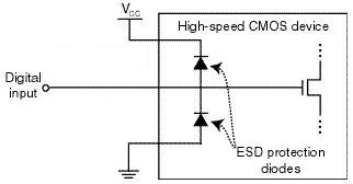
image from raspberrypi.org
In a typical chip, both protection diodes probably have a standard 0.6V drop. If the input goes below -0.6V, the bottom diode will begin to conduct, clamping the input voltage and preventing it from going any lower. If the input goes above VCC + 0.6V, then the top diode will begin to conduct, similarly preventing the input voltage from going any higher. When either diode conducts, a large amount of current may flow through the diode, depending on the resistance of the digital input line, and the output impedance of whatever’s driving it. I’ve failed to find any specifics on the CPLD’s diodes, but it seems they’re normally designed to tolerate very high voltages and currents, but only for a very brief time – like a few nanoseconds. Try to pass even a modest DC current through the diodes, like a few milliamps, and they may burn out.
In the case of this CPLD with its 5V tolerant inputs, I’m guessing the top diode actually has a drop of 2.2V instead of 0.6V (or it’s a few diodes in series with a 2.2V total drop). So under normal operation with a 3.3V supply for VCC, that diode wouldn’t begin to conduct until the input voltage exceeds the CPLD’s maximum rating of 5.5V. But despite the difference in voltage drop, the theory should be the same as with a standard ESD diode.
What’s going to happen if VCC is actually much lower than 3.3V, or zero? Then the diode will begin to conduct when the input voltage exceeds 2.2V, and it will keep conducting as long as this condition persists, or until it burns out. So how much current can the diodes tolerate, and for how long? I don’t know, and haven’t been able to find any straight answers, but I’ve seen estimates between 0.1 mA and 50 mA for max ESD diode current, with potential damage from transients that exceed that level for as short as a few milliseconds or even microseconds.
I don’t have any hard data to prove this theory, but it’s consistent with the observations I’ve made and with behavior reported by other people using the same CPLD in other applications. So until a better theory comes along, I’ll assume the problem is blown ESD protection diodes.
Possible Solutions
There are 12 I/O lines between the Mac and the CPLD. 10 of these are CPLD inputs: 5V signals from the Mac connected to the CPLD’s 5V tolerant inputs. One is a CPLD output: a 3.3V signal that’s still high enough to exceed the Mac’s 5V Vih threshold for a logical “1” value. The last can be an input or an output, depending on which kind of disk drive is being emulated. So I need a solution that ameliorates or prevents an over-voltage situation on 11 input pins, while also enabling one of those pins to be used as an output sometimes.
Inline Resistors – The simplest and cheapest solution is to add inline resistors in the signal paths of all 12 signals. Under normal operation, the inputs draw negligible current, so there will be negligible voltage drop across those resistors and the function of the circuit will be unaffected. But in an over-voltage situation where the CPLD’s VCC supply is too low and the ESD diode begins to conduct, the resistor will limit the current to a level that’s safe for the diode.
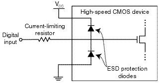
image from raspberrypi.org
The tricky bit is choosing what resistor value to use. There’s some parasitic capacitance on the cable, the board trace, and the CPLD input itself, and this capacitance combined with an inline resistor forms a classic RC circuit. The input voltage will no longer be able to change as rapidly before, rounding the corners of signal edges, and reducing the maximum signal switching rate that’s possible. So too high of a value for the resistor is bad. Fortunately the disk drive signals are comparatively slow, in the 1 or 2 MHz range at most. I estimate I could use a resistor as large as maybe 3.3K ohms before this RC filtering affect would cause problems, but I may be way off.
But wait! The resistor also needs to protect the ESD diode by limiting the current, and too low a value for the resistor will be ineffective. The minimum resistor size depends on the characteristics of the ESD diode, which are unknown. Let’s assume it has a 2.2V drop, and can tolerate 1 mA max. With a 5V input and the diode terminated to ground, that would leave 2.8V across the resistor, so a 2.8K ohm or larger resistor would be needed in order to limit the current to 1 mA.
Would this solution work? Probably, and it would only cost about $0.12 on top of the ~$1.20 assembly cost. But the overlap of resistor values is uncomfortably narrow between “too high for the circuit to work” and “too low to offer any protection”. And the values themselves are based partly on guesswork rather than any hard numbers from a datasheet. Some people feel that relying on the ESD diodes in any way is bad form, and the absence of real specs for the diodes is one reason why. Anyone with experience who might suggest an appropriate resistor value here that would satisfy both requirements – I’d love to hear from you.
Resistors with External Diodes – What about implementing my own over-voltage solution, external from the CPLD, with an inline resistor and a diode up to 3.3V for each signal? This would essentially do the same thing as the ESD diode, but with a beefier diode capable of handling more current, and for which I would know the actual specs. With a beefier diode, I could also get away with a smaller inline resistor, so the RC filtering effects would be reduced.
Standard silicon diodes with a 0.6V drop probably wouldn’t work. When the CPLD’s power supply is below the magic 1.5V threshold, its inputs aren’t 5V tolerant, but it’s not specified exactly what voltage is safe in this situation. If we assume 3.6V is the highest safe voltage, then the diode would need a voltage drop less than 0.3V.
The biggest problem with this approach is the number of parts required, and resulting cost. With a separate resistor and diode on all 12 signal lines, that would be 4 new pins/pads per signal line, or 48 new pins total. The assembly cost alone would be almost $2.00, without even considering the cost of diodes, pushing this solution to the point where it would cost more to implement than it would save. Maybe there’s some kind of single-chip ESD circuit solution I could use, that has a bunch of appropriate resistors and clamp diodes built into it? That might help bring the pin count down to a more manageable level.
Voltage Dividers – Another approach is to use a pair of resistors in series for each signal line to form a voltage divider. Something like this:
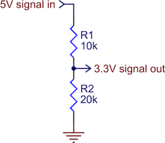
image from pololu.com
As long as the resistor values were in the proper ratio, and the 3.3V input itself drew minimal current, this would work OK as a level converter. It would prevent 5V signals from ever reaching the CPLD. The downside of a voltage divider is that when the 5V input is high, there’s current constantly flowing to ground. The IWM chip in the Mac is only able to source a paltry 0.32 mA for a high-level output, and to limit the current to that level, the combined resistance of the two resistors would have to be at least 15.6K ohms. That’s an awfully large resistance, and would probably create the types of unwanted RC filtering effects I feared would interfere with normal circuit operation. Using voltage dividers would also double the total number of components required for circuit protection, relative to inline resistors.
Level Shifter – The last solution I’m considering is a few level shifter chips. Any kind of chip would do, as long as it had non-inverting buffer outputs at 3.3V, with fully 5V-tolerant inputs. Candidates are the 74LVC244, or the 4050B. This would prevent any signal voltage above 3.3V from ever reaching the CPLD. With one input and one output pin per I/O signal, the number of pins and the assembly cost should be about the same as with passive resistors. A quick look at the 4050B shows I could buy a pair of them, enough to buffer 12 signals, for about $0.35 in quantity. That might work.
The problem with using level shifters is that they’re unidirectional. What about that one signal that’s either an input or an output, depending on the type of disk drive being emulated? This solution wouldn’t work for that, so I would need some additional bidirectional protection circuitry just for that one signal. I’m not sure what that might be or how complex it would become.
The other drawback of using level shifting chips is that they’re comparatively big, and it might be difficult to find space for them on the board without relocating everything and re-routing the whole thing from scratch. Resistors and diodes, even in multi-element packages, tend to be smaller and easier to squeeze into tight spaces.
Suggestions?
Have I analyzed the economics or the electronics wrong? Any other good solutions that I overlooked? Please leave your suggestions in the comments.
Read 19 comments and join the conversation19 Comments so far
Leave a reply. For customer support issues, please use the Customer Support link instead of writing comments.
For the bidirectional pin, something like the solution used in this SFE bidirectional level converter could work? https://www.sparkfun.com/products/12009
I confess to having no idea how that circuit works, and from the comments it looks like it only works with open collector outputs? But hey, could be useful – The entire solution for one signal line is a single transistor and a pair of resistors.
There’s also the TI TXS/TXB0101/4/8, which are full bidirectional level converters with 1/4/8 IO respectively – a bit expensive for the bigger ones, but the one-bit versions are available in SOT23 and about 40 cents in 100 quantities. http://www.ti.com/product/txs0101 http://www.ti.com/product/txb0101 – unsure which one would work in this application, if either – different I/O pin behavior.
http://www.digikey.com/product-detail/en/TXS0101DBVR/296-22863-1-ND/1740010
http://www.digikey.com/product-detail/en/TXB0101DBVR/296-21664-1-ND/1534255
Thanks for the links! On further reflection, I don’t really need true bi-directional I/O for that last pin. In one configuration it’s a CPLD output, in another configuration it’s a Mac output *whose value I can ignore*. So with a unidirectional level shifter, I think I could configure that pin as if it were always a CPLD output, and then add an inline resistor between the level shifter output and the Mac to handle the case where they’re fighting.
well its good you are looking into this 🙂 The whole CLPD thing for me has me worried to even use my EMU’s
after the 7th blown clpd i replaced it and sat my emu’s up on the shelf to look pretty… I do have that patch adaptor you made that has the resistor pack on it.. i just have been so DARN busy i haven’t had the pleasure of sitting down and testing it with one of my emu’s maybe this week… seems like as fantastic as the CLPD is, to me it seems like it needs to be shielded from being on the front line. So maybe a resistor pack is what the doctor ordered?
Where I work, each board in a piece of equipment has zeners for each pin in addition to whatever protection the chip might offer by itself… But then again, failure where I work could cost over 100k… I know it would be costly, but why not a zener for every pin on the DB19?
Also, the back of my Floppy EMU is covered with kapton tape to help prevent any ESD issues, Maybe you should survey everyone who has issues and ask them whether they had a case or not, how where they holding it etc…
do you think the CLPD , ones it takes a static hit… maybe the next step is melt down?
if that is the case there is not much steve could do to fix that … right?
Since the diodes are easily tested, (just measure from input to GND or VCC) I recommend doing a diode test on every pin of a blown CPLD to determine if the diodes are the problem. I would also make sure the parts are handling properly; the ESD protection is only so good.
Good thought, but am I missing some obvious way to test the ESD diodes? With the chip mounted on the board, I can’t measure the diode path independently of everything else, and there are all kind of potential current paths through multiple chips. Using a known good board and the diode test mode on the multimeter, I was able to measure a forward voltage drop of 0.677V from GND to each CPLD pin, which looks reasonable as the bottom ESD diode. But I couldn’t measure any forward drop from the CPLD pin to 3.3V, nor from the pin to GND. In fact, I measured a forward drop of 0.794 in the other direction, from 3.3V to the pin, which doesn’t make sense as an ESD diode. Maybe if I desolder the chip from the board, and try to solder fine gauge wire to each pin, I might be able to measure the ESD diodes in isolation. But that sounds pretty difficult, and destructive.
Murdock might be onto something… As much as one wants to trust his suppliers, something is bound to get out of compliance. Regarding ESD, thou art a bitch! Just one zap, and you can partially destroy a chip. The chip is still functional, and it will pass all tests. But down the line, days, months or even years later, it will break. This Apple training video from the mid-1980s convinced me a long time ago how destructive and stealth ESD damage can be. https://www.youtube.com/watch?v=2WNb3TUNf0A
Maybe I’m wrong to suspect the ESD diodes. The CPLD datasheet says “The 3.3V VCCINT power supply must be at least 1.5V before 5V signals are applied to the I/Os”. Or as restated in a different version of the datasheet “External I/O voltage may not exceed VCCINT by 4.0V.” These mean the same thing, since 5V signals can technically go as high as 5.5V, which is 4.0V above 1.5V.
Where does 4.0V come from? That sounds less like a diode forward voltage, and more like some kind of transistor breakdown voltage. My knowledge of transistors at this level is weak, but I know there are max voltage ratings for a transistor’s gate to source voltage, and mysterious things like body diodes to consider. If the transistor is being damaged due to exceeding a max voltage rating, then it’s actually the input voltage itself that’s the issue, and not the current that results from the voltage. There should actually be negligible current, until the transistor breaks down and is destroyed. With negligible current flowing, an inline resistor wouldn’t create a voltage drop, and so it wouldn’t help anything. Basically, I’m thinking that an inline resistor will only help if damage is caused by high current (in the ESD diode), but not if damage is caused directly by high voltage without high current (transistor breakdown).
I have one good clue that suggests it *is* a current problem, and inline resistors would help. To my knowledge, this issue has only appeared when using a Mac with a SWIM floppy chip, and never on the oldest Macs with an IWM floppy chip. This leads me to believe that the issue is not related to accidental ESD damage during assembly or later handling, else it would appear in all Mac models. The IWM is a TTL chip with a max high current drive of only 0.32 mA per the datasheet, so it’s just not capable of driving much current into the CPLD. But I believe the SWIM is a CMOS chip, and while I don’t know its specs, it probably has a much higher max high current drive around 10 or 20 mA. Both chips put out the same 5V, but maybe the higher current driving capacity of the SWIM combined with some evil transient glitch can cause damage. If that’s the case, an inline resistor should protect it by limiting the current.
Interesting test results: I decided to stop talking theory, and do as much real-world testing as possible. So in the name of science I sacrificed two boards and intentionally destroyed them. Ouch! Normally hot-plugging is not supported, and there’s a warning against it in the instructions, but I tried repeated hot-plugging of the board as a way to hopefully trigger the suspected input transient.
Board 1: Hot plugged 100 times in a IIci, 100 times in an LCIII, rapidly power cycled 100 times in an LCII. Finally tried hot plugging with a IIsi, and the CPLD died after only 6 times. So for hot-plugging, my IIsi seems to be the CPLD-killer of my computer collection.
I used a hot air rework station to remove the dead CPLD and replace it with a new one. Then I built an external adapter with 1K series resistors on all the data lines. Tested the board again with the series resistors, and performed 100 rapid power cycles and 1000 (yikes!) hot plugs on a variety of different Macs, including 500 hot plugs on the IIsi. I also tested floppy and HD20 emulation with the 1K series resistors, on seven different Macs, to make sure the resistors didn’t interfere with normal operation. No problems encounted, all good.
Board 2: Connected the adapter with 1K series resistors, and tried 100 rapid power cycles and 800 hot plugs without encountering any problems. Then I removed the series resistor adapter, tried a hot plug on the IIsi, and the CPLD died on the first attempt.
The weird thing was with board 1, after replacing the dead CPLD and testing 1000 hot plugs with the series resistor adapter, I then removed the adapter and tried to kill it a second time with more hot plugging. I couldn’t do it! I tried 600 hot plugs without the adapter, including 400 on the IIsi, but nothing affected it. It was like my hand-soldered replacement CPLD was immune to further problems. Yet it’s the exact same chip type and speed grade as the one it replaced.
As I understand it, on the input side there is a p-channel MOSFET connected across the output and VCC of the chip, like this:http://i.stack.imgur.com/8zx4g.gif. I think that 4V is the max gate-emitter voltage, making it 3.5V between 1.5V and 5V, but the full 5V if VCC is at ground. Parameters like that are not tightly controlled, and can vary by over a volt from chip to chip, explaining the inconsistent failures. I highly doubt those transistors are avalanche rated, so while resistors may appear to work, they could very well just delay the problem.
Possible solutions:
-If the Mac has an output enable, disable it until the 1.5V is up to spec.
-Add a discrete level shifter.
-Look for a compatible CPLD with better specs.
-Add a tristate buffer and only enable it once the 1.5V bus has settled.
Although this begs another question: If there is no diode from input to VCC, what protects it from ESD in the first place? Could there just be a 5.5V zener diode to ground, fulfilling both positive and negative discharges?
Although likely not the problem, I would also check all of your fanouts.
Also, what are the CPLD symptoms? I would expect only the one input section to be destroyed if my above hypothesis is correct, unless that results in a permanent short circuit condition.
Sorry, I didn’t follow your sentence about the gate-emitter voltage. Should this be gate-to-source voltage, since we’re talking about a MOSFET? In this case, is the p-channel MOSFET’s source the “VDD” terminal from your linked diagram? This is a 3.3V CPLD with 5V tolerant inputs, so there’s no 1.5V supply or bus: using the terminology of the diagram, VDD will be 3.3V under normal operation, and Vgs of the p-channel MOSFET will be either +1.7V or -3.3V depending on whether the input is +5V or 0V. But if VDD is 0V while input is +5V, then Vgs will be +5V.
I found a discussion on the Xilinx forums involving a similar-sounding problem, with the same CPLD family I’m using. The Xilinx rep said the “input cannot exceed VCCINT by 4.0 V” rule is more of an issue regarding metal migration over a significant portion of time, and that it would take “eons” for migration from hot-plug transients to have an effect. http://forums.xilinx.com/t5/CPLDs/XC95144XL-Latchup-Failure/td-p/331
So maybe this whole 4.0V thing isn’t a problem at all. Maybe it’s the ESD diode just as I originally suspected, and the series resistors are protecting against ringing or overshoot that would otherwise be present.
> If there is no diode from input to VCC, what protects it from ESD in the first place?
Yes, that’s strange. I assume the diode is there, but I’m unable to detect it using my test methodology with the chip already soldered into the circuit. In fact, there must be a much more complicated input stage than I’ve imagined, since this is a 3.3V chip with 5V tolerance, but which also has a separate VCCIO, so the switching thresholds of the input buffer transistors would need to be controlled somehow to adjust if VCCIO is 3.3V or 2.5V or whatever.
> Also, what are the CPLD symptoms?
VCCINT (3.3V) and GND appear shorted, with about 1 ohm resistance. The chip draws large amounts of current and gets very hot.
Yes, I meant gate-source. My knowledge of that particular chip is pretty much nonexistent, but you got what I was saying. My guess as far as metal migration, and this is just a guess, is because the inputs are internally current limited and avalanche current is flowing through the gate and source. Although at this point that seems irrelevant.
Although the fact that the problem occurs during hot swaps and not assembly makes me think the ESD protection circuitry is not the issue.
I imagine the board you have mass produced is either wave soldered or reflowed in an oven…
What if the CPLD isn’t liking whatever is done to it thermally during production and assembly?
Also I’m just going to jump out on a limb here and make a guess.. shouldn’t you be powering VCCio after VCCint so that it comes up with the weak pullup rather than the undefined state with them possibly driving voltages (which the MAC would probably shoot through and burn something up)?
Yes, I think supply startup sequencing would be the most conservative approach, but comparatively complex and costly to implement relative to the other solutions, and wouldn’t help guard against transients that occurred after startup.
Have you ever stuck a logic probe on there to see if you could even observe these events?
Also, from what you said before, with the rep saying that hot plug transients not really being problematic I would expect that the transients really aren’t the problem but the random state the outputs are in when it isn’t properly powered up in a safe sequence is. Basically it leaves the pins vulnerable during the hotplug.
Also couldn’t you just put an RC circuit on VCCio that can supply enough current to your pins but also have a period where it delays the appearacne of voltage on VCCin at reset/hotplug. I know alot of chips have reset circuits that do things like this. Although I may be oversimplifying it a bit.