

Zener Regulator Trouble
In my attempts to resolve some logic level problems with the Yellowstone Tester, I decided to take a crude approach, and reduce the 5V supply to about 4.7V using a simple zener diode voltage regulator. From my previous tests with a variable voltage supply, the reduced voltage at 4.7V was enough to get the tester working nicely. But now when I try combining a fixed 5V supply with a resistor and a 4.7V zener, I find that it doesn’t work as expected. Zener regulators apparently don’t behave the way I thought they did, and for this specific circuit, they may not work at all.
The problem is that the rated voltage of a zener diode is only valid for a specific level of current. I knew this, but I thought the voltage would only change a small amount over a wide range of current: perhaps 100 mV of change for the 10 mA to 100 mA range where my circuit operates. In other words, I thought the IV curve for the zener would be very steep, nearly a vertical line.
This proved to be a bad assumption. Using a 1N4732A zener, at a current of 90 mA I do see 4.7V on the zener, but the voltage is only 4.506V at 40 mA, 4.459V at 30 mA, 4.335V at 20 mA, and 4.212V at 10 mA. That’s not good. It’s non-linear, but if it were a resistor then its value would be about 6.1 ohms. I’m not sure how I was meant to know this from the datasheet, which doesn’t include any IV curves. The datasheet does include a dynamic resistance (impedance?) number, but I thought that was for AC applications since it’s specified for a frequency of 1 kHz.
Voltage Regulator Says What?
So how are you supposed to build a voltage regulator using a zener with this amount voltage of variability? The standard way to build a zener regulator is with a resistor in series with a zener, and a load in parallel with the zener:
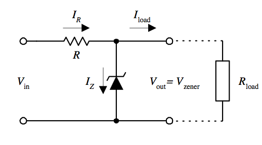
If Vout is ever higher than VZ, then the zener will pass more current, which also increases the current through the resistor, which increases the voltage drop across the resistor and lowers Vout. So Vout gets “regulated” to the value of VZ, so long as the current through the zener remains constant.
If the circuit has a fixed load, then the value of the resistor can be chosen to get the desired current through the zener to achieve the nominal zener voltage. But if the circuit has a variable load, there’s a problem. In order to maintain a regulated output voltage, the voltage drop across the resistor must remain unchanged while the load current changes. That means the current through the resistor must also remain unchanged. The only thing that will change is how much current flows through the load and how much flows through the zener. If the load draws less current, then the zener must draw more, in order to keep the total current constant.
Let’s say the load current can vary between 10 and 100 mA, and the zener can theoretically handle 150 mA before it burns up. For safety’s sake you probably don’t want to push the zener all the way to 150 mA though, so you might limit it to 120 mA. You could choose a resistor value to achieve a constant current of 130 mA through the resistor, which can be divided between the zener and the load 120/10 mA for light loads anywhere up to 30/100 mA for heavy loads. That’s a 90 mA range of currents through the zener, so for a 6.1 ohm equivalent resistance you would see a 0.549V change in the output voltage. That’s not very well regulated at all.
If I’ve analyzed this all correctly, then a zener voltage regulator basically doesn’t work unless the load current never varies by more than about 10 to 20 mA. That’s a pretty lousy regulator. I’m not sure how I never realized this about zener regulators before.
Plan C
So now what? I still need to get the Yellowstone Tester working. The original 5V circuit has problems with the logic levels, and Plan B for reducing the supply voltage to 4.7V with a zener seemingly doesn’t work either. Would I be better off with a simple Schottky diode in series with the 5V supply input? This wouldn’t be perfect either, since the nominal 5V supply might actually be closer to 5.1V or 4.9V, and the voltage drop across the diode will change with the load current. But I still think it would be enough to keep the voltage within a range of about 4.8V to 4.5V, which is better than I’ll get with the zener.
Read 7 comments and join the conversation7 Comments so far
Leave a reply. For customer support issues, please use the Customer Support link instead of writing comments.
Hmm, my thinking about the zener may be wrong. There may be some feedback happening that results in better regulation of the output voltage than I first thought. If the current through the zener is small, causing the output voltage to be substantially lower than 4.7V, that means the voltage drop across the resistor will be larger than the expected 0.3V. And that means the current through the resistor will also be higher. The load current won’t change, so all the extra current will flow through the zener, raising the output voltage closer to 4.7V.
I tried making a simple simulation, and the output voltage only varied about +/- 0.1V over the range of load currents. So it may be OK after all.
Going from 5V to 4.7V is indeed a tricky problem to do in a simple manner. If you had more volts to spare then things would be much easier.
(1) Would some extra loss help? You’re already losing power in the upper resistor and the zener, perhaps try adding a resistor in parallel with your load and see if that allows you to tune your zener’s output to a smaller range.
(2) Schottky sounds good, but you may still want to add an extra loss resistor to keep its vdrop sufficiently high. This will probably end up more stable overall than the zener option.
>So now what?
74avc4t245
74avc8t245
SN74LXCH8T245
74avc16t245
74ALVC164245
and so on, why screw with bad logic levels at all?
This is a one-off tester board I’m attempting to get working with a few cuts and patches. There are 80 I/Os so it wouldn’t be practical to patch in 10 new bus ICs. If I were manufacturing many copies of this design, then I’d start over with a different port expander that supports 5V TTL levels, and avoid this whole issue.
Enough talk… I patched in the zener components, and it looks like this will work. Over an input voltage range of 4.9V to 5.1V, and a load of about 15mA to 80mA, the zener kept the voltage between 4.6V and 4.75V. I calculated the power dissipated in the zener ranged from 285 mW to 615 mW. It’s theoretically a 1W zener, so this should be OK.
I could still go back and try a series Schottky diode instead, but I think the output voltage range would have to be worse, since any variation in input voltage would be passed to the output. The only advantage I see to a series Schottky is that the power dissipated in the diode would be slightly lower, about 300 mW at worst.
I think I’ll let the Schottky version run for an hour while configured for max power dissipation in the zener. If it’s still alive at the end of the hour, I’ll call it good.
If you’re still looking for a better Zener diode or equivalent part, may I suggest the TL431? It’s a TO-92 part with three terminals and acts as an adjustable Zener diode. You can set the regulation voltage with a pair of resistors. It’s a very common part in PC power supplies and similar switch-mode PSUs, where it’s used as a voltage regulator. But I don’t know how well it regulates with a variable current, nor do I know its maximum current capacity.
One pitfall of the TL431: you can’t easily whack a capacitor on its output (like you would a voltage regulator). Many capacitance values make it unstable, check the datasheets. Worst of all: different brands/makes of TL431 have different regions of stability 😐 some very forgiving, others showing charts that look like rain storms.