

Archive for the 'Floppy Emu' Category
Macintosh DiskCopy 4.2 Floppy Image Converter
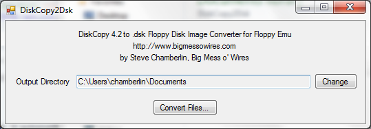
Here’s a quick-and-dirty utility I whipped up called DiskCopy2Dsk. A few people asked how to create raw .dsk floppy images to use with Floppy Emu. The hardware supports both DiskCopy 4.2 and raw .dsk image files, but DiskCopy 4.2 images are treated as read-only, so .dsk images are preferred. However, many emulation sites have their entire collection in DiskCopy 4.2 format.
On a vintage Mac, DiskDup+ will create .dsk images, or convert between DiskCopy 4.2 and .dsk images.
For 21st century computers, this DiskCopy2Dsk utility will bulk-convert DiskCopy 4.2 image files into .dsk format. It received at least 45 seconds of testing, so I’m sure it’s good. Source code is included for the curious.
DiskCopy2DSK for Windows
DiskCopy2DSK for Mac OSX (Intel Macs only)
Cameron Kaiser contributed this command-line version of dc2dsk, which works on PPC or Intel Macs. The source code has been rewritten for any generic Unix system, so that Linux and NetBSD users can play too.
Read 11 comments and join the conversationFloppy Emu Back in Stock
Macintosh Floppy Emu is back in stock. The elves have been working overtime to build more of these. Get yours today before they sell out again!
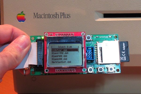
Floppy Emu is a prototype floppy disk drive emulator for vintage Macs. It uses an SD memory card and custom hardware to mimic a 400K, 800K, or 1.4MB 3.5 inch disk drive and floppy disk. It plugs into the Mac’s external or internal floppy connector, and behaves exactly like a real floppy drive, requiring no special software on the Mac. Floppy Emu is available now for $89.
Read 1 comment and join the conversation
Floppy Emu – Ready For Sale
The Floppy Emu Macintosh Disk Emulator is finally available for sale! Get one now for $89. Each one is hand-assembled, programmed, and tested by me. After more than two years in development, and two months of preparation for “production”, I’m very excited to share this with you today. The initial inventory is quite small, but should grow over the next few weeks as more boards get built.
Floppy Emu is a prototype floppy disk drive emulator for vintage Macs, compatible with everything from the original Mac 128K through the Mac II and Power Mac series. It uses an SD memory card and custom hardware to mimic a 400K, 800K, or 1.4MB 3.5 inch disk drive and floppy disk. It plugs into the Mac’s external or internal floppy connector, and behaves exactly like a real disk drive, requiring no special software on the Mac. Floppy Emu is perfect for setup or troubleshooting of a Mac without a hard drive or a working OS. Just plug in the Floppy Emu, and you’re booting up in seconds. Keep it as a permanent solution, or use System 6/7 installer disk images to do a new hard drive installation. The hardware is also great for moving files between vintage Macs.
As always, you can also build your own if you’re comfortable with SMD soldering and have the necessary programming tools.
Thanks to everyone who offered feedback, advice, and encouragement over the long course of development. It’s great to be part of such a positive community!
Be the first to comment!Manufacturing is Hard
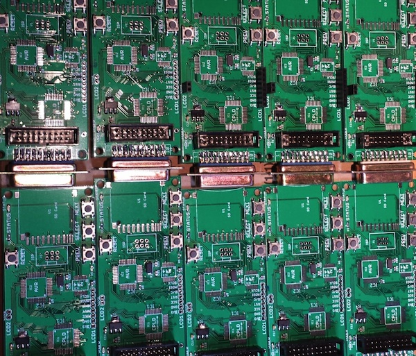
There’s a big difference between building one of something, and making a repeatable process to build 10 of them, or 100. Unfortunately I’m learning that the hard way while I try to get some more Floppy Emu boards ready to sell. If I had any hair, I’d be pulling it out! I never thought this would be so hard.
If you haven’t been following the earlier posts, Floppy Emu is a floppy disk drive emulator for vintage Macintosh computers. I built the first Floppy Emu for my personal use about a year ago, and while the soldering was a little challenging, everything worked once it was done. I posted the design on the BMOW web site, and since then I’d estimate about 10 other people have built their own Floppy Emu boards. Then in October I built two more boards from my remaining parts stock, and sold them on eBay. I tested those thoroughly before I sold them, so I’m confident those boards were working well.
The eBay sale generated lots of interest and requests for more boards, so in late October I created board revision 1.1 in preparation for a small hand-made “production run”. The board layout changed slightly to make room for mounting holes, and some board traces were moved or added. I switched to a different PCB supplier, changed to a different brand of 3.3V LDO regulator, and substituted the Atmega1284 for the Atmega1284P to save a few pennies.
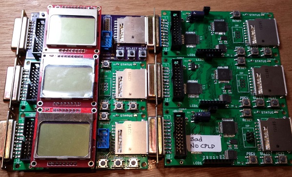
I built four of the rev 1.1 boards, and initially none of them worked. As described in my previous post, the new brand of 3.3V regulator proved to be unstable when combined with the output capacitor I’d been using. The oscillations on the 3.3V and 5V supply lines caused all kinds of crazy behavior and malfunctions that drove me crazy. I’ve since found that replacing the 10 uF ceramic output capacitor with a 33 uF tantalum solves that particular problem. Yet even with the capacitor fix, one of the boards exhibited occasional random write errors, and I somehow toasted another one during assembly.
Later I discovered a flaw in my CPLD firmware that was shorting the Mac’s PWM drive speed control input to GND. Floppy Emu doesn’t actually use that input, but shorting it to ground is not very nice, and may have damaged the CPLD, the Mac, or both. This only affected the rev 1.1 boards. That firmware flaw is now fixed, hopefully without any permanent damage.
I’ve since built two more of the rev 1.1 boards. One worked fine, but the other showed the same pattern of occasional random write errors. Of the six rev 1.1 boards I’ve built, that means I only have three working boards. Arghh! 50% yield is not good. The random write error is maddening. It doesn’t happen very often, so it’s necessary to do a LOT of testing before I can be confident a particular board does or doesn’t have this problem. I spent a long time with a lens, an oscilloscope, and a debugger trying to explain what’s going wrong, but failed. My best theories are:
Software Bug – Perhaps there’s a problem with the Floppy Emu software, like a timing bug or uninitialized variable, and tiny variations in boards or components cause the bug to appear or disappear. This was my first guess, but if true I would expect a continuous distribution of bugginess across boards, rather than two groups of “working” and “not working” boards. I tested the working boards heavily, and they really do work 100%. I also made many experimental software changes that I thought might cause the problem to appear or disappear, but there was no change in behavior. And to my knowledge none of the rev 1.0 boards have this problem, even though they use the same software.
Soldering Mistake – I may have created a bad solder joint somewhere, leading to flaky behavior. That’s possible, but it seems pretty unlikely I’d make the exact same soldering mistake twice in six boards. And I’ve visually inspected the problem boards carefully with a 10x magnifier, and touched up all the likely problem points with an iron, without any success.
CPLD Damage – Some of the CPLDs might have been damaged by the firmware bug that shorted PWM to GND, resulting in buggy behavior even after the firmware was fixed. That’s certainly possible, but then why weren’t all the CPLDs damaged? Why just two of them? If this is the true explanation, then future rev 1.1 boards should all work OK now that the firmware bug is fixed.
Atmega1284 vs Atmega1284P Variation – Maybe some minor difference between the two types of the AVR microcontroller is causing unexpected problems. As far as I know, the only difference is that the “P” version uses Atmel’s Pico-Power system to enable very low power sleep modes. Since I’m not using those sleep modes, that difference shouldn’t matter.
Board Design Flaw – The rev 1.1 board could contain a design mistake not present in the original board, like substantial coupling between neighboring traces, signal reflections, or other noise that leads to intermittent problems. While the layout changes between rev 1.0 and 1.1 were minor, I can’t rule this possibility out.
Manufacturing Flaw – The rev 1.1 boards from Smart Prototyping might not be built to the same tolerances as the original boards from Dorkbot PDX. In terms of published specs like minimum trace width and spacing, the Smart Prototyping process should be fine, and I used their design rules file to verify my board in Eagle. I know other people have been successful with rev 1.0 boards not made by Dorkbot PDX, though I don’t think any have used Smart Prototyping specifically.
Unfortunately I’m at one of those points where I really don’t know where to go next. I could build a few more boards to test the CPLD damage theory. Or get some more Atmega1284P’s and build a few boards with those, or experiment with going back to the original PCB manufacturer or the rev 1.0 board design. But each of those experiments would require more time and money to test the theory. I’d need to see at least five good boards and zero bad ones before I had any confidence that I’d solved the problem. Spread across all the possible problem causes, I could end up building several dozen test boards, and still come up empty-handed if the true cause is a software bug or something else I haven’t considered.
Read 11 comments and join the conversationNew Floppy Emu Boards and Supply Noise
I finally got the new Floppy Emu revision 1.1 boards! Rev 1.1 has a few minor tweaks to prepare for selling assembled hardware. I built four of them with a soldering mini-marathon, and three of them work. The fourth I think I toasted somehow, but I’ll check it in more detail later. 75% yield isn’t so good. 🙂
Unfortunately something isn’t quite right. With the new boards I’ve built so far, I’m seeing anywhere from 3X to 10X more noise on the 5V and 3.3V supply lines, and I think this is causing random resets and spurious interrupts and other phantom problems. The noise is very regular, with a frequency of between 80 kHz and 130 kHz on both supplies. I was able to bring the supply noise under control by soldering an extra 10uF capacitor between the 3.3V and GND pins on the LCD, but it shouldn’t need one, since there’s already a 10uF cap between 3.3V and GND on the main board. Yet the difference with and without the extra cap is like night and day:
Rev 1.1:
new LCD (with extra 10 uF cap) and SD card: 80 mV noise on 5V supply, 100 mV on 3.3V supply
new LCD and no SD: 60 mV on 5V, 50 mV 3.3V
old LCD and SD card #1: 380 mv on 5V, 100 mV on 3.3V
old LCD and SD card #2: 840 mv on 5V, 280 mV on 3.3V
old LCD and no SD: 900 mv on 5V, 340 mV on 3.3V
Rev 1.0:
new LCD and SD card: 100 mV on 5V, 120 mV 3.3V
new LCD and no SD: 80 mV on 5V, 120 mV 3.3V,
old LCD and SD card: 100 mV on 5V, 120 mV 3.3V
old LCD and no SD: 80 mV on 5V, 100 mV 3.3V
I guess I could just go with the extra capacitor on all new boards, and call it done, but I’d really like to understand what’s going on. Quite a few things changed between revisions, any of which could affect supply noise:
- New board design relocated some parts and re-routed some traces
- Boards were manufactured by a different fab
- Using an ATMEGA1284 instead of ATMEGA1284P
- Different brand of 3.3V regulator
I’m tempted to blame the 3.3V regulator, but I don’t quite see how it could be at fault. The old regulator from rev1.0 and the new regulator from rev1.1 are virtually identical.
I’m going to do some more experiments before deciding how to proceed. If you’ve got any ideas on what to check, please leave a note in the comments!
Read 12 comments and join the conversation
Getting Ready to Sell

I’m almost ready to start selling Floppy Emu hardware! My plan is to offer two options: a fully assembled and tested unit, and a “DIY kit” containing the PCB board, LCD, and DB-19 connector. These are the hardest parts to find, and the ones where shipping costs kill you if buying individual quantities, so the DIY kit should be helpful for people making their own builds. The assembled units will be hand-built and tested by me, and I’m a little scared about signing myself up for that much labor. If there’s enough demand I’ll look into having an electronics assembly shop do the work, but I expect large quantities are necessary for that to be economical. I haven’t decided on prices yet, but it’ll be low enough that people find it a good value, while still high enough to make it worth my time and effort.
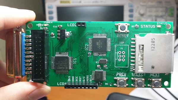
Meanwhile, feature development continues. I’ve completed a revision 1.1 board, which has a number of small changes:
- LCD backlight
- mounting holes (can build a case for the board)
- support for the lock tab on the SD card
- removed the motor LED, since motor status is now displayed on the LCD
- removed the unused JTAG connector footprint
- repositioned the buttons and status LED
- added a test point for oscilloscope probing
- probably some other things I forgot
I also added support for Disk Copy 4.2 disk images, long filename support, and subdirectories on the SD card (see photo). Things were getting a little out of hand once there were more than a few dozen disk images on the SD card, and the subdirectories really help. This makes OS installs almost enjoyable! Just download the disk images from Apple, copy them to your SD card, boot the Mac from the Install Disk 1 image, and off you go.
The last major piece of the puzzle is 1.4 MB write support. I’ve got this partly working already, and writes of individual sectors and small files are OK, but writing a larger file to a 1.4 MB emulated floppy causes things to go haywire. The lack of any real debugging tools (other than printing to the screen) makes this a pain to troubleshoot, but I think I’m pretty close to resolving it.
Read 8 comments and join the conversation