

Archive for the 'Tiny CPU' Category
Power Research
 I’d like Tiny CPU to be flexible with its power requirements. The Tiny Test Board that I made uses an external, 5V regulated power supply, and so doesn’t have any on-board voltage regulation. That works fine, but I’d like the flexibility to use other unregulated power supplies too, and especially the option to use battery power. That’s going to take a bit of work.
The supply current measurements that I took recently showed about 150 mA used by the test board, but the demands of the real Tiny CPU board will be much higher. The Tiny CPU board will have a second CPLD, RAM, and ROM that the test board lacks, adding another 150 mA or so. It’s also likely that I’ll substitute a large graphical LCD for the small text LCD on the test board, requiring still more current. 400 mA is probably a good guess for the total current needs of the real Tiny CPU board.
400 mA is not a trivial amount of current. If I used a 9V power supply, the drop across the voltage regulator would be 4V, and power dissipation would be 4V * 400 mA = 1.6 Watts. That would probably require a TO-220 voltage regulator with a heat sink. If I used a 12V power supply, the power dissipation would be even higher, at 2.8 Watts. In theory I could use a lower voltage supply, like 6V or 7V, depending on the the capabilities of the voltage regulator used. However, 9V is the lowest voltage commonly available.
Battery Power
Powering the Tiny CPU board from a battery would make it totally self-contained. OK, a full-size PC keyboard isn’t very portable, but I could still make some interesting programs using only the buttons and switches on the board itself. Unfortunately, finding suitable batteries looks like it will be more difficult than I thought.
My first idea was to use a 9V battery. Who knew that Energizer publishes the datasheets for all their batteries? Examining the 9V alkaline datasheet was disappointing. It only has a capacity of about 500 mAh, and that’s at a discharge rate of 100 mA. It also assumes the battery is discharged all the way to 4.8V– too low for electronics. At a 400 mA discharge rate, the situation is even worse:
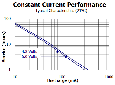
The 400 mA discharge rate is off the chart, somewhere in the sub-1-hour lifetime range. Yuck.
If not a 9V alkaline battery, then what? Sanyo Eneloop AA and AAA rechargeable NiMH batteries are among the best rechargeables currently available. Four AA Eneloops would provide a total voltage of about 5.4V, with substantially more capacity than the 9V alkaline battery:
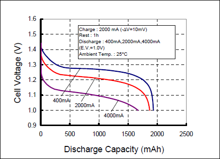
Fully charged, each battery is roughly 1.4V, providing 5.6V total. The cell voltage drops rapidly, though, flattening out at about 1.25V per cell and 5.0V total, while providing 4 hours of useful battery life.
That seems like a good solution, except that it doesn’t provide enough extra voltage to operate a voltage regulator. Even using a LDO (low-dropout) regulator, it typically needs at least 5.5V input in order to get 5.0V output.
Here, then, would seem to be my options:
- Spend a lot of money on 9V batteries. Works, but not very economical.
- Use five AA batteries. Works, but… five batteries? Typical battery holders are one, two, or four batteries. It just seems strange.
- Use four AA batteries, without any voltage regulator. Works… sort of. With four fully-charged batteries, the total voltage of 5.6V would be pushing the limits of safe operation, although it would quickly fall into a more reasonable 5.0V range. This would preclude using any higher voltage wall power supply, though, and so doesn’t seem like a great option.
- Add a switch to allow optional bypassing of the voltage regulator. The regulator could be used with wall power supplies, 9V batteries, and the first minutes of use for AA batteries, then bypassed as the AA’s lose voltage. Works, but dangerous. If I forgot that the regulator was bypassed while connecting a higher voltage supply: poof, toasted board.
Option 2 is probably the best bet, but using five batteries just kind of offends my sensibilities. I’m still searching for a better solution.
Read 9 comments and join the conversationCPU Angst
I’m starting to fear that Tiny CPU is a short-sighted design. It occupies a strange spot between ultra-simple soft-CPUs like MCPU, and much more capable soft-CPUs like PicoBlaze. The hardware is nearly as complex as PicoBlaze, but the functionality is not so much better than MCPU, making it a poor trade-off. The 10-bit address space and lack of true pointer support (no generic indirect addressing mode) are especially limiting.
The project is far enough along that I’ll finish it anyway, so it will be a good learning experience if nothing else. Next time if I do a “Small CPU” project, substituting even a very small FPGA for the two CPLDs I’m using here should allow for dramatically improved functionality.
Supply Current
I took some power measurements for my test board, at various clock speeds and with different peripherals connected.
| 1.22 MHz | 4 MHz | 8 MHz | 20 MHz | |
|---|---|---|---|---|
| with keyboard and 20×2 LCD | 142 mA | 147 mA | 145 mA | 148 mA |
| with LCD only | 141 mA | 143 mA | 144 mA | 147 mA |
| no peripherals | 89 mA | 100 mA | 101 mA | 105 mA |
Conclusions: Clock speed and the presence of a keyboard have little effect on the current draw. A 20×2 line text LCD adds about 50 mA. I also tried a 20×4 LCD, which draws about 65 mA.
The LCD current is higher than I expected. The datasheet for the 20×4 LCD says the supply current should be just 4 mA, but I assume that’s without the backlight. The datasheet doesn’t say much about the configuration of the backlight LEDs or their current needs, and whether they’re in series, parallel, or both, except to note that VLED is 4.2V. That probably means there are two LEDs in series, or possibly several series pairs, connected in parallel.
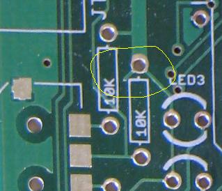
As I type this, I realize I’ve made a mistake. If the backlight drops 4.2V, then 0.8V should be dropped across my current limiting resistor. If I want 15 mA (pretty typical for an LED), then the resistor should be 0.8V / 15 mA = 53 Ohms. But I’m actually using a 15 Ohm resistor, and I don’t remember how I came up with that value. With that resistor I should see 0.8V / 15 Ohm = 53 mA going to the backlight, plus 4 mA for the controller chip, so 57 mA. That’s not far from what I measured, so at least that makes sense.
Beep!
I also did some experiments generating tones with a simple speaker. Directly driving the speaker with a digital output pin works, but draws about 15 mA with a 50% duty cycle square wave. Using the digital I/O to switch a transistor on and off instead delivers 50 mA to the speaker, making it noticeably louder while also reducing the current demands on the CPLD. It does require adding a handful more passive components to the board, though: in addition to the transistor itself, it needs a resistor to limit the base current, and a flyback diode in parallel with the speaker to discharge reverse voltage created by switching.
Serial Port
Next up: working on a soft-UART serial port, for communication with a PC. I’m not sure how that will get used ultimately– maybe a bootloader? I’m sure it will prove useful, though.
Be the first to comment!Board Test Success!
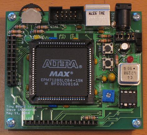
Hot diggity damn, it works! It took me about four hours to fully assemble the Tiny CPU test board with all the components, which was good soldering practice. The surface-mounted navigation switch was a little challenging, but not too bad. Here’s how it looks after everything has been soldered in place:
I built the board up in stages, with stage one being the power section, and stage two being the JTAG header and CPLD socket. After that, I was able to connect the board to my PC, and get the JTAG programming software to talk to it successfully. With that first checkpoint passed, I was confident the rest of the assembly would go fairly smoothly.
Once the assembly was finished, verifying the correct function of the buttons, navigation switch, and LEDs only took a few minutes. The LCD and keyboard interfaces proved to be more challenging, since I had to implement the behavior using basic Verilog logic instead of any kind of microcontroller or CPU. I had hoped to make a demo of reading keys from the keyboard and echoing them to the LCD, but unfortunately that wasn’t possible, because there’s no on-board memory in which to store the scan code conversion table. Instead, I made a demo in which the keyboard scan codes themselves are displayed on the LCD.
Without any kind of on-board RAM or ROM, I felt like I exhausted the possibilities of this board pretty quickly. A 128 macrocell CPLD without other support logic just doesn’t do anything very interesting. I guess that’s fine, though, since the whole point of this exercise was to get some PCB design practice, and get the experience of building a real board before moving on to the more complex board needed for the full Tiny CPU design.
I predicted I’d find four mistakes in the board design, but I only found two issues that I would call “mistakes”. Fortunately I was able to work around them both. Aside from those mistakes, I also found several other areas in which the design could be improved.
Mistakes
Reset circuit – The reset IC I’m using has separate output pins for the reset and /reset signals. Reset is a standard logic output, but /reset is open drain, and requires a pull-up resistor. I missed that little detail, and didn’t include a pull-up. To work-around the problem, I bent the /reset pin up and cut it off, then jumpered reset to /reset on the underside of the board, and changed the CPLD logic to expect an active-high reset signal instead of active low. You can see the cut-off pin at the bottom-right of the photo above. It’s pin 6 of the DIP-8.
PS/2 connector footprint – The PS/2 connector I bought had three through-hole “feet” for mechanical stabilization, in addition to the six signal pins. The footprint I used in Eagle only has one foot. My fix was to cut the other two feet off before mounting the connector on the board, which sacrifices some stability, but has no other negative effects.
Areas to Improve
Edge placement – The JTAG connector, PS/2 connector, and power connector all hang slightly off the edge of the board, which wasn’t intentional.
Component spacing – Components are packed in a little too tightly in a couple of places. All those little 0.1 uF capacitors surrounding the CPLD socket have to bend outward slightly, because they rub the socket’s outer wall. In retrospect, I should have left a little more breathing room between everything when doing the layout.
Expansion header power – The expansion header on the left side of the board doesn’t have any power or ground connections, limiting its usefulness. Instead, all the expansion pins are connected to CPLD I/O pins. Oops.
Test points – I didn’t include any test points or convenient places to connect an oscilloscope probe or signal tester. At least a spare pair of power and ground pins would have been handy.
JTAG connector – It would have been better if the JTAG connector were rotated 180 degrees. In the current orientation, the cable has to drape over the board, instead of off its edge. You can see this in the video.
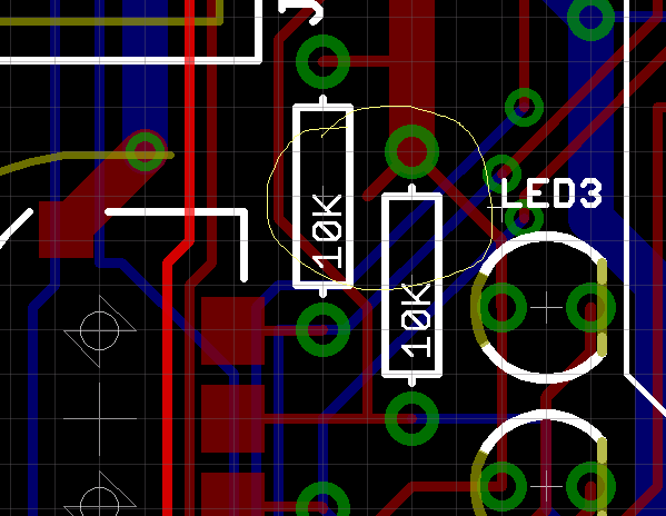
Signal trace to nowhere – I must have forgotten to clean up an old trace completely while I was routing. During assembly, I noticed this signal trace that leads nowhere.
Got Board
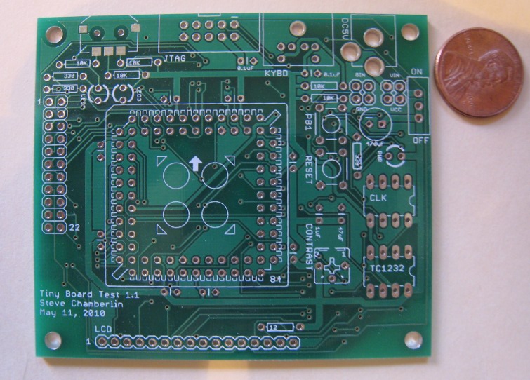
My “Tiny Board Test” custom-designed PCB is here! The BatchPCB order took 18 days from design submission to delivery, but it seemed like an eternity. It’s pretty awesome to see my ideas rendered in copper and fiberglass. Somebody might even mistake me for one of those professional electro-whatsit engineers. Shhh, don’t tell anyone I’m making it all up as I go!
I actually received two boards, although I only ordered one. This seems to be common with BatchPCB. Because they don’t perform any electrical testing on the boards, maybe they make up it for it by sending extras?
The drill registration on this board is not great. You can see in the photo that all the drill holes are offset slightly above-left of the pads, especially noticeable in the top-left corner of the board. It’s close enough that I think it should still work OK, though. The second board (not pictured) has much better drill centering. Both boards are routed with nice straight edges– it’s the extreme close-up perspective of the camera that makes the edges look curved here.
I did some cursory electrical testing, and everything seems fine. I guess there’s nothing for it but to solder on all the parts, and see if it works? Let’s take bets on how many errors I’ll discover in my original design during the assembly process. My guess is four!
Read 5 comments and join the conversationBits of Progress
Lots of good news on the Tiny CPU front!
I successfully programmed a Flash ROM via the JTAG indirect method today. Woohoo! I was never able to get it to work previously, and couldn’t figure out why. Several possibilities:
Comically long, loopy wires connecting the CPLD to the Flash? These were pretty much guaranteed to act as antennas and pick up noise. I replaced them with neatly wire-wrapped connections.
Questionable software? Previously I was using a demo copy of the commercial program TopJTAG Flash Programmer. When I tried to program the Flash, it would just time out. I switched to using a free, command-line JTAG/Flash tool called UrJTAG.
Unsupported Flash type? I switched to a 512KB AM29F040B, instead of the smaller capacity AM29F010B. I’m not sure it really mattered, but the AM29F040B was specifically mentioned as a supported Flash type for UrJTAG.
Unconnected VCCIO? The CPLD demo board I bought from eBay appears to have a design flaw. The VCCIO pins are all connected to each other, but not to anything else! I only discovered that by accident. I’ve now connected them to 5V.
I changed all four things at once, and now it works. The programming speed is about 400 bytes/second. That sounds pretty horrible, but it’s actually not bad. Programming an 8K block took 22 seconds to write, and an additional 16 seconds to verify. That’s plenty fast enough, so I don’t think I need a separate bootloader.
What’s even more exciting is that I got the ship confirmation email from BatchPCB today! That’s 15 days from design submission to shipped boards, which isn’t as bad as I’d expected it to be, but it still seemed like an eternity. This is only my test PCB, though: it only has a single CPLD (Tiny CPU will have two), and no RAM or ROM. It should prove that my basic PCB design will work, though.
Progress on “making things smaller” is going well too. I got some 32-pin PLCC Flash ROMs, which can still be unsocketed and put into a stand-alone programmer if necessary, but are only about a quarter the size of a comparable DIP. Here’s a comparison:
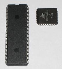
I’m also getting more confident in my surface-mount soldering skills, to the point where I’ll probably look at replacing some of the other components like the RAM with smaller, surface mount versions. Now that I’ve got JTAG indirect programming working, I could theoretically switch to an even smaller surface mount Flash ROM package too. I’ll probably keep the PLCC version, though, so I can retain the option for stand-alone programming in an emergency.
Be the first to comment!Small ROM
In my ongoing effort to make the Tiny CPU board as small as possible, I’m looking for a small Flash ROM or EEPROM. That’s small in physical size, not necessarily capacity. My search has led me to examine many different ROM package types and interfaces, but unfortunately I’ve yet to find anything better than a standard Flash ROM in a 32-pin DIP package, using a space-hogging ZIF socket, with reprogramming performed by removing the ROM to a stand-alone programmer.
JTAG?
My dream solution is a programmable ROM with a JTAG interface. Then I could add the ROM to the JTAG chain, and program it using the same hardware and software I’ll already be using to program the CPLDs. Unfortunately, the only JTAG ROMs I’ve found are intended for use as FPGA configuration devices, and have a serial interface instead of the standard parallel address and data lines I need. They’re also surprisingly expensive.
SPI, I2C?
I’ve seen a couple of ROMs that use SPI or I2C for programming, but that doesn’t help me much. I don’t have any appropriate programming hardware, and at any rate these also don’t have parallel address/data interfaces. I do have an FTDI USB-to-serial cable, which might be usable for programming if I had appropriate software and a serial-programmable, parallel addressable ROM.
JTAG Indirect?
An approach with some promise is JTAG indirect programming, in which the ROM’s pins are connected to some other JTAG-enabled device, and then JTAG boundary-scan bit shifting is used to manipulate those pins to program the ROM indirectly. This might work, but available information and software for actually doing it seems scarce. I’d need some better examples, and some software that actually does indirect programming, before I could evaluate it. ROM programming using the JTAG indirect method is also reportedly slow, but just how slow isn’t clear. If it takes several minutes to program a 128K ROM, I would probably get annoyed.
Custom Interface?
I might use a standard Flash ROM in a smaller package, soldered directly to the board, and connected to a simple microcontroller or other device used to program it. That would be essentially equivalent to JTAG indirect programming, but rolling my own solution. The addition of a MCU or other programming hardware would mostly cancel out the space savings of the smaller IC package, though. Creation of a ROM-image loader also likely wouldn’t be trivial.
DIP.
It seems that all paths lead back to where I started: A plain old DIP, in a ZIF socket for easy plugging and unplugging. It will take up a lot of space, but I can easily transfer the ROM back and forth between the Tiny CPU board and my EPROM programmer whenever I need to update the ROM image. Maybe this is one case where the old, tried and true solution is best.
Read 16 comments and join the conversation