

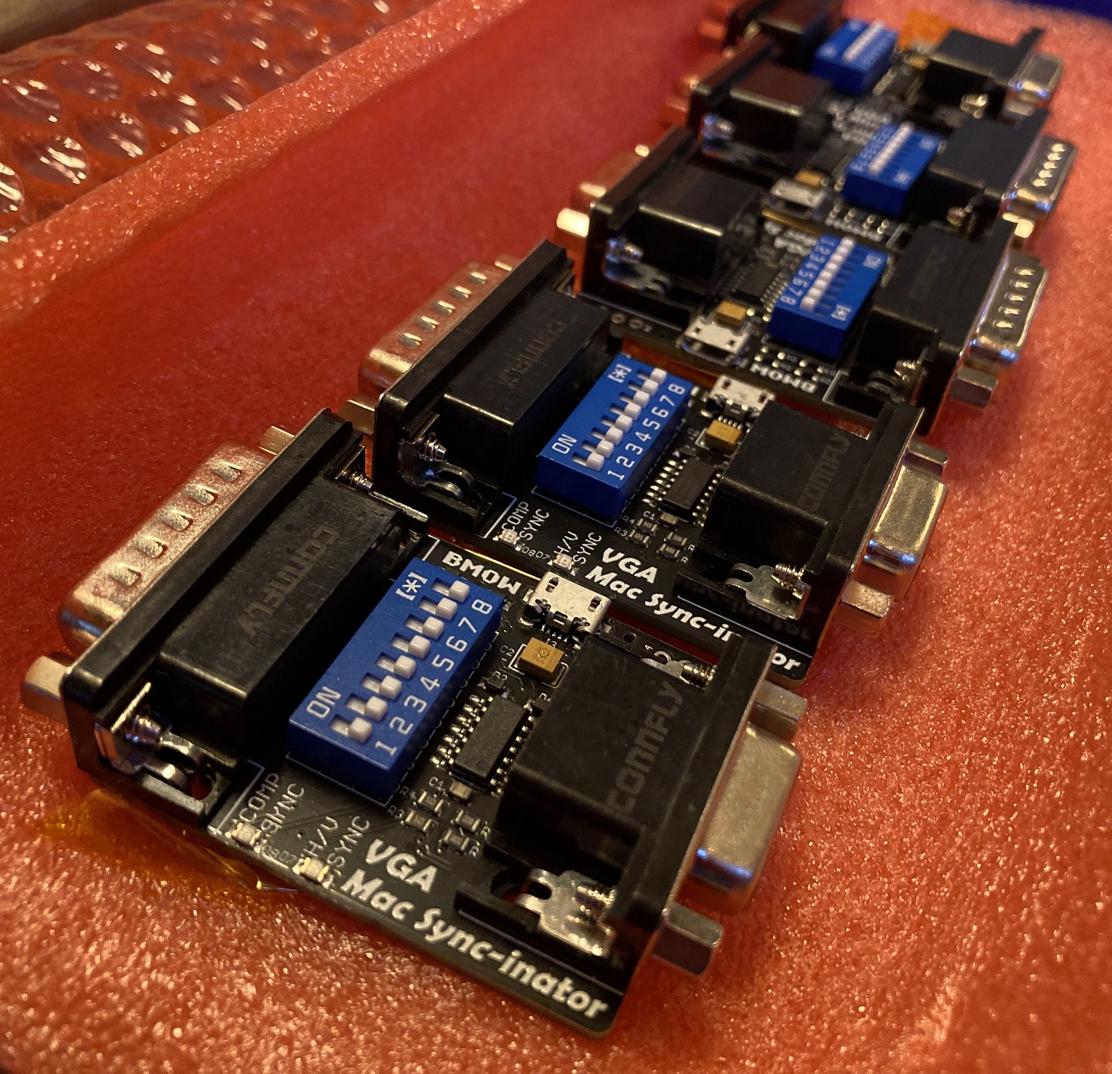
Mac Sync-inator VGA Sync Converter Launches Today!
Today I’m very excited to officially announce a new addition to the BMOW product lineup: the Mac Sync-inator VGA sync converter. I’ve been talking about this project for months, and it’s been available in small quantities while I gathered customer feedback, but now it’s finally ready for the bright lights and prime time. If you own a classic Macintosh or Apple IIgs computer, and have ever struggled to get it working with a standard VGA monitor, then the Mac Sync-inator is for you.
The Sync-inator is an adapter for connecting Apple video sources (DB-15) to VGA monitors (HD-15), with active sync processing circuitry that sets it apart from typical passive video adapters. There’s a built-in microcontroller that analyzes the incoming sync signals in real-time, automatically selects the best adapter settings, and can optionally reprocess the sync signals into a different format for better compatibility with some VGA monitors. You can even view a debug log of diagnostic and technical information about the video signal, as seen by the Sync-inator. For video format nerds as well as for people who want something that “just works” with minimum hassles, there’s a lot to be excited about here.
Sync-inator Benefits
- Three different sync processing modes, for wider compatibility than other VGA adapters
- Automatic sync mode selection, for easy setup
- Sync activity LEDs for quick troubleshooting feedback
- Serial port output of video signal diagnostic info
- Plus all the other capabilities of standard VGA adapters
What is this and why should I care?
In short, the Sync-inator makes it possible to use many types of VGA monitors that previously wouldn’t work with your classic Apple video source due to sync compatibility issues. It also removes much of the frustration that’s typically associated with using passive DIP switch VGA adapters, by using a microcontroller to automatically configure some of the adapter settings. It will do everything that common passive Mac-to-VGA adapters will do, plus more. If you’ve got a monitor that stubbornly refuses to work with your vintage Mac video card, give the Sync-inator a try.
Sync-inator is not a video scaler, and it doesn’t modify the video resolution or colors in the RGB video signal. Only the sync signals are affected.
What the heck is sync?
The video signal from your computer or video card contains synchronization information which helps your monitor detect the beginning of each new line and new frame. There are several different ways in which this sync information can be encoded. Some computers only support specific sync methods, and some VGA monitors can only handle specific sync methods. If your monitor can’t handle the sync signals from your computer or video card, then you’ll have a problem, even if the monitor supports the video resolution and frame rate.
In the world of classic Apple computers, the two most common sync methods are composite sync and separate sync. With composite sync, the horizontal and vertical sync information is combined into a single output signal. With separate sync, horizontal and vertical information is transmitted with two distinct sync signals. Some computers can only output composite sync, or can only output separate sync. Some computers output one or the other at different times, depending on which specific video resolution is active. Some computers output both composite sync and separate sync simultaneously.
The Sync-inator is able to convert a composite sync signal into separate horizontal/vertical sync signals, using several different methods. It’s also able to analyze the incoming sync signal and make an educated guess about which conversion method is best, although this choice can be overridden if you prefer a different method.
What’s wrong with my computer? Is it even working?
The Sync-inator also has two built-in LEDs for debugging and troubleshooting video problems. If your monitor remains dark and no image appears, the LEDs can provide information to determine if the problem is with the monitor, the computer, the choice of video resolution, or something else. One LED will light whenever a composite sync signal is present, and the other LED will light whenever a separate sync signal is present. If neither LED is lit, then your computer isn’t outputting any video, and you’ll need to troubleshoot the source. If one or more LEDs are lit, but the monitor doesn’t show any image, then you’re likely dealing with some kind of unsupported video mode and will need to troubleshoot the monitor itself.
Debug Log
The Mac Sync-inator has a serial port where debug logging information is provided. The debug log is an optional feature, and all the Sync-inator’s capabilities can be used without ever looking at the log. But advanced tech nerds may find the log info interesting. To view the log, you can attach a USB serial cable to the TXD and GND terminals at the edge of the Sync-inator PCB, and set your terminal software’s serial port speed to 57600 bps. The debug log lists the current sync processing mode, including the result of the automatic processing mode’s analysis, as well as the period and frequency of the detected sync signals and other technical information. Here’s an example showing an Apple “Toby” NuBus video card running at 640×480 @ 67 Hz resolution.
* BMOW VGA Mac Sync-inator, v 1.0

sync mode: choose automatically

detecting sync signals...

hsync no

vsync no

csync yes

csync horiz period 28.5 us, freq 35.0 kHz

csync vert period 15.0 ms, freq 66.3 Hz

auto-select: convert csync into hsync and vsync

csync: pulse width 9 20 871, period 142 285 1003
Get your Sync-inator Now
For details on the Sync-inator, usage instructions, or to make a purchase, please see the main Sync-inator page at the BMOW web site. I hope this new device will be as useful for you as it has been for me!
Read 3 comments and join the conversationMac Sync-inator Update
I’m beginning to see the light at the end of the tunnel for my Mac Sync-inator Mac to VGA adapter. The hardware is essentially final now, and all that remains are software tweaks, which are mostly related to the new composite sync splitter behavior. Along the way I’ve amassed a large test fleet of different monitors and an even larger number of Macintosh and Apple-compatible video sources, and testing all those combinations has been very slow.
Elevator Pitch
The Sync-inator is a small in-line dongle that aims to be a “pro version” of the Mac to VGA adapters you likely already have, and that takes some of the frustration out of the Mac-to-monitor setup dance, and enables some new combinations of video sources and monitors to work together that were previously incompatible.
The Sync-inator works by rerouting, modifying, or splitting the sync signals from the video source before they’re sent to the monitor. It’ll do everything that common Mac to VGA adapters (e.g. Belkin) will do, plus more. Sync-inator is not a video scaler, and the timing and resolution of the RGB video signals are not modified in any way, only the sync.
The Sync-inator’s “normal” features are:
- DIP switches to set the desired video resolution. Settings for common resolutions are printed on the back of the device.
- Configurable passive methods of sync pass-through, like a sync switch matrix.
The “pro” features of the Sync-inator over standard VGA adapters are:
- Micrcontroller-driven active splitting of a composite sync signal into separate hsync and vsync signals. This is essential for older video sources that only provide composite sync. Although some monitors can handle composite sync or sync on green directly, many can’t, and for those monitors a composite sync splitter is required. This is what motivated this project initially, trying to get my Mac IIci built-in video working on one such monitor.
- Auto-detecting and auto-configuration of the sync behavior, reducing the typical setup hassles experienced with other adapters. If it senses that hsync and vsync signals are already present, it’ll simply pass them through. If those signals aren’t present, then it’ll kick over to composite sync splitter mode.
- Sync-inator has two LEDs that will visually show whether the video source is outputting composite sync, separate h and vsync, both, or neither. This should further reduce setup hassles, by making it easy to distinguish between cases where there’s no picture due to sync/resolution compatibility problems versus cases where the video source isn’t outputting anything at all.
- Sync-inator has a serial port that will dump a bunch of diagnostic info about the video source and its characteristics and timing. That’s fun for video nerds, and maybe useful for something.
“Sync splitting” is a slightly misleading term, because it sounds like there are already two signals that simply need to be separated. In reality it’s more like “sync generation”, synthesizing two wholly new hsync and vsync signals using the csync signal as a reference. This is straightforward in theory, but in practice it’s proven challenging to get every timing detail 100 percent right. Along the way I’ve discovered that some monitors care about certain aspects of hsync and vsync that others don’t seem to: like whether they trigger from the hsync falling edge, rising edge, or both edges, their sensitivity to changes in hsync pulse width, and their tolerance for small amounts of jitter in sync signal edges.
Apple IIgs Testing
The Apple IIgs uses the same DB-15 port as early Macintosh computers for connecting RGB monitors, so I wondered whether the Sync-inator could also be made to work on the IIgs. The answer is mostly yes, although there are a few things to watch for. Although the IIgs uses the same pins as the Mac for RGB signals, grounds, and composite sync, some of the other pins are different. On the Mac, three pins are used as a Sense ID to set the desired video resolution, but the IIgs uses one of these same pins for a -5V power supply. It doesn’t need a Sense ID since it always outputs the same video resolution. Unfortunately this means one of the Sense ID DIP switch combinations will connect the IIgs -5V supply to GND. This isn’t fatal, but it prevents the IIgs from turning on, and it’s definitely not good. For IIgs use, the Sense ID switches can all be turned off.
Another challenge for the IIgs is the horizontal sync rate of 15.7 kHz, which is much lower than typical monitors will support. Even if the sync signals are all good, most monitors will refuse to display the RGB video from a IIgs. For testing purposes I bought a Samsung SyncMaster 512N specifically because it was reported to work at 15 kHz with the IIgs. Unfortunately it was a bust. The 512N’s activity LED would turn green and the backlight would turn on, but no picture would appear. The monitor’s front panel buttons were also unresponsive, as if the monitor firmware were frozen. I tried the IIgs’ RGB video in composite sync splitting mode, as well as sync-on-green and csync-to-hsync modes, with the same results every time. The failure in csync splitting mode could be a flaw with the Sync-inator, but the other modes should definitely have worked since this monitor supports 15 kHz as well as SOG and csync-to-hsync (I confirmed its sync support with some other video sources).
So I started doing some digging. In the manual for the 512N, it lists 30 kHz as the lowest supported refresh rate, not 15 kHz. Then I found a handy web page with a big list of older monitors and brief reports of their 15 kHz support. This page lists the 510N’s 15 kHz capabilities as “partial”. It doesn’t have an entry for the 512N, but I think they’re the same thing with and without audio speakers. The other SyncMasters in the same product series were also listed as “partial” or “no”.
After doing more reading, this leads me to believe that 15 kHz may be an undocumented feature that may only work on some 512N samples. Either Samsung changed the internal design during the product’s lifetime without changing the model number, or it’s a question of engineering tolerances and manufacturing variability whether 15 kHz works or not. In my case, the answer seems to be “not”.
Update: I later discovered that the IIgs was in PAL mode (50 Hz refresh). After switching the IIgs to 60 Hz vertical refresh, the 512N behaved identically to the VE228H described next.
A Second 15 kHz Monitor
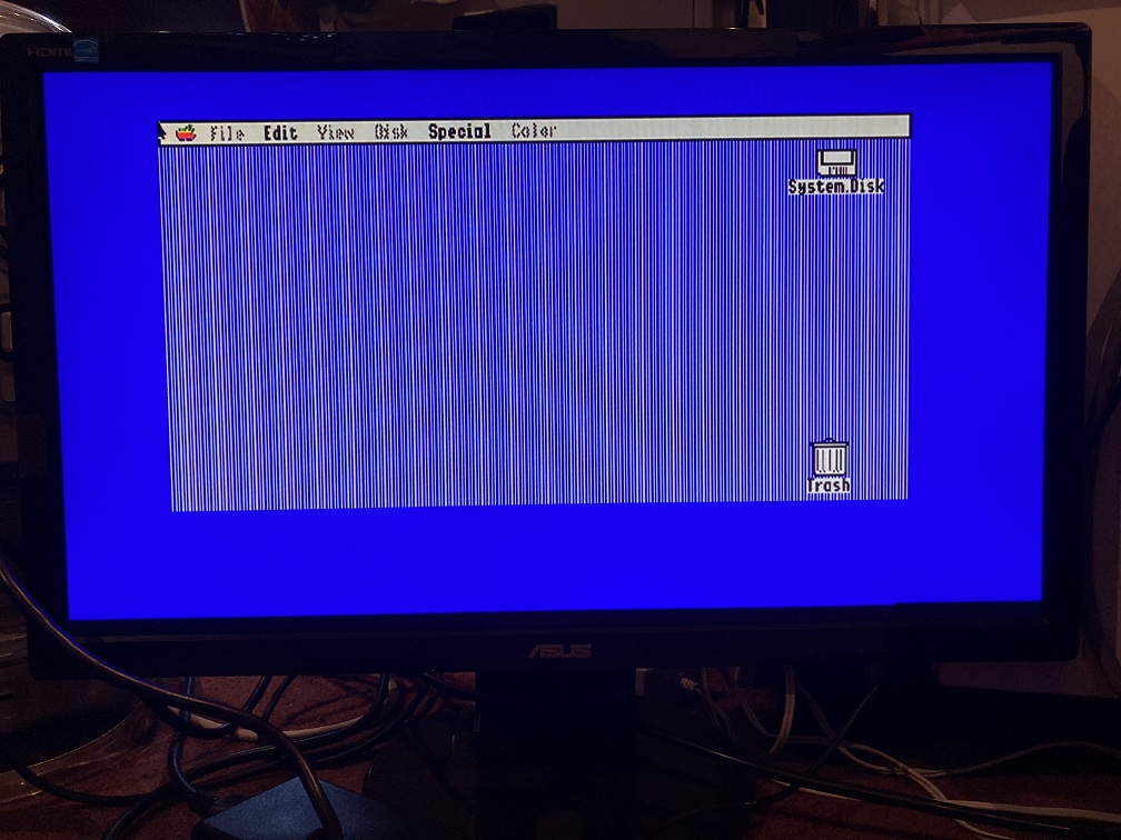
But hang on, that handy web page also lists the Asus VE228H as having full 15 kHz support, and that just happens to be one of the eleven monitors in my growing fleet of test equipment. So I hooked up the VE228H in sync-on-green mode, and it worked! The title photo shows an Apple IIgs GS/OS desktop output via the Sync-inator on the VE228H. I also tried the mode where csync is sent to the monitor’s hsync input, and that worked too, even when I physically cut the green video line to be certain the monitor wasn’t sneakily using SOG.
Sadly the Sync-inator’s csync splitting mode didn’t work on the VE228H – mostly it just showed a blank screen or “out of range” error. That’s OK because csync splitting isn’t needed in this particular case, since one of the other sync modes can be used instead, but it meant that something wasn’t quite right with my 15 kHz csync-split signal. That might eventually be a problem in other settings with other monitors. I spent a long time fiddling with parameters and attempting to hand-tune the resulting sync signals to be as good as possible, and while I did succeed in getting the IIgs video to appear for brief moments, I never found a combination that worked reliably.
Is this a failure? Looking at that 15 kHz web page list again, most of the comments for monitors that worked say that they were tested with a simple passive adapter, without any fancy sync processing. The Sync-inator can do that too, as my tests showed. A 15 kHz csync splitting mode would only be relevant in cases where somebody has a IIgs and a 15 kHz monitor, but the monitor only supports 15 kHz on its separate hsync/vsync inputs and can’t support that same signal as sync-on-green or csync-to-hsync. The comments on the web page would suggest that’s a rare situation, maybe non-existent. Manufacturers that include 15 kHz support probably know that they’re targeting older computers and game consoles where composite sync and SOG are common.
Given all this, I’m planning to remove explicit IIgs support from the csync-splitting code, since it doesn’t work in its current incarnation, and since most of the time it should be possible to use another sync mode with the IIgs (assuming a 15 kHz monitor). Removing the IIgs-specific code would have other benefits too, slightly simplifying the main loop code for csync splitting and enabling it to run a bit faster, which might also help in other areas.
Status and Next Steps
With that, I think I’ve nearly reached the end of compatibility testing. One significant change made recently is the addition of a feature that dynamically changes the microcontroller’s system clock speed depending on the supply voltage it detects. The Sync-inator is normally self-powered, drawing its supply current from the sync signals themselves, and the supply voltage varies depending on the particular Mac or video card being used. Higher clock speeds require higher supply voltages. This clock speed adjustment allows for slightly more precise csync splitting behavior when sufficient voltage is available, but has no effect on the other passive sync translation modes.
“Normal” Mac-to-VGA adapter behaviors are now 100 percent working, including setting the desired video resolution through DIP switches, and choosing a passive sync translation mode. This matches the capabilities of other Mac-to-VGA adapters.
For troubleshooting help, the csync and hsync/vsync activity LEDs are working, and the serial port output is working. The default DIP switch setting for the sync mode is also “automatic”, which aims to reduce guesswork.
For the Mac IIci and IIsi, composite sync splitting is 100 percent working on every monitor that I’ve tested. That was my main goal, and it’s met. This enables the IIci and IIsi to work on a wider selection of monitors than before.
I’m fairly certain there aren’t any other Macintosh models whose built-in video doesn’t output separate hsync/vsync signals and that would benefit from csync splitting. Among plug-in video cards, I’ve only found a few early cards from the 1980s that don’t output separate hsync/vsync. For the Macintosh Monochrome Card, composite sync splitting with the Sync-inator is working out-of-the-box with 90 percent of monitors tested, and the one exception also works if an external 5V power supply is used. That’s great.
The Toby Nubus video card has a strangely different csync signal than others. It works with all of the monitors tested, but has a few quirks. For a small number of monitors, an external 5V supply for the Sync-inator is needed when using csync splitting mode. One “Planar” brand monitor balks at the csync splitting signals from the Toby, but automatically switches over to sync-on-green which works. I’d rate the csync splitting support for Toby as 4.5 out of 5 stars.
The SuperMac ColorCard SE/30 is another oddball. It fares similar to the Toby, working with all of the monitors tested but requiring a 5V Sync-inator supply when used with some fussier monitors. The benefit of a 5V supply appears to increase for higher resolution video modes. The Planar monitor behaves the same as with the Toby card, switching over to sync-on-green. I’d rate the csync splitting support for this SuperMac card as 4.5 out of 5 stars.
Although I’ve focused heavily on csync splitting in this discussion, most of the time csync splitting mode won’t be needed, because you’re not using a crusty old video source with composite sync or else because your monitor supports SOG or csync-to-hsync. Those common cases are completely working, 5 out of 5 stars.
I still need to clean up a few loose ends here, but I’m hoping I can finally finish this project soon.
Read 10 comments and join the conversationMac-to-VGA Composite Sync-Splitter Progress
I’ve been continuing the design development on a Mac-to-VGA video adapter with an integrated composite sync splitter, whose concept was first discussed in October, with a first-generation prototype following shortly after. To recap: some Macintosh models like the Mac IIci and IIsi and some Apple video cards like the Toby card output a composite sync signal, instead of the more common configuration with separate horizontal and vertical sync signals. VGA monitors don’t have a composite sync input, but some monitors will accept csync if it’s connected to their hsync input. For VGA monitors that lack this feature, the IIci/IIsi/Toby/etc simply won’t work, no matter how the DIP switches are configured on a passive VGA adapter.
My goal is to design an active Mac-to-VGA video adapter with the ability to process an incoming csync signal and generate new signals for hsync and vsync, thereby enabling the IIci/IIsi/Toby/etc to work on standard VGA monitors and LCDs. This sync translation should be optional, so the adapter can also be used similarly to a standard passive Mac-to-VGA adapter, and it can support the widest possible variety of computers, video cards, and video modes. I’m happy to report that I’m very close to this goal.
An active adapter needs a power source, and the first challenge of this development effort was that the Macintosh video port doesn’t provide any power. The port only has ground connections and data signals, but no handy +5V supply pin. I’ve settled on a design that uses phantom powering, drawing current from the sync input signals themselves in order to power the adapter’s circuitry. While this is generally considered a bad design practice, I’ve been able to keep the adapter’s total current consumption low enough that phantom powering doesn’t interfere with the normal functions of the sync signals. I prefer this solution over requiring an external power source, since it enables the active adapter to be used identically to passive adapters. Just plug it in to the video port, and it works.
The first-generation prototype used an LM1881, a specialized sync-splitting chip that can generate a new vsync signal from a csync input. The LM1881 can’t generate an hsync signal, however. This prototype worked with some monitors that I tested, but not others. I considered replacing the LM1881 with other more advanced sync-splitting chips, but they’re more expensive and more rare. After some experimentation I decided to use a small microcontroller instead of a dedicated sync-splitting chip, since it would be more flexible, cost less, and consume less power than a dedicated sync splitter. That decision was the foundation for this second-generation prototype, which I’m tentatively calling the Mac Sync-inator.
Generation Two: VGA Mac Sync-inator
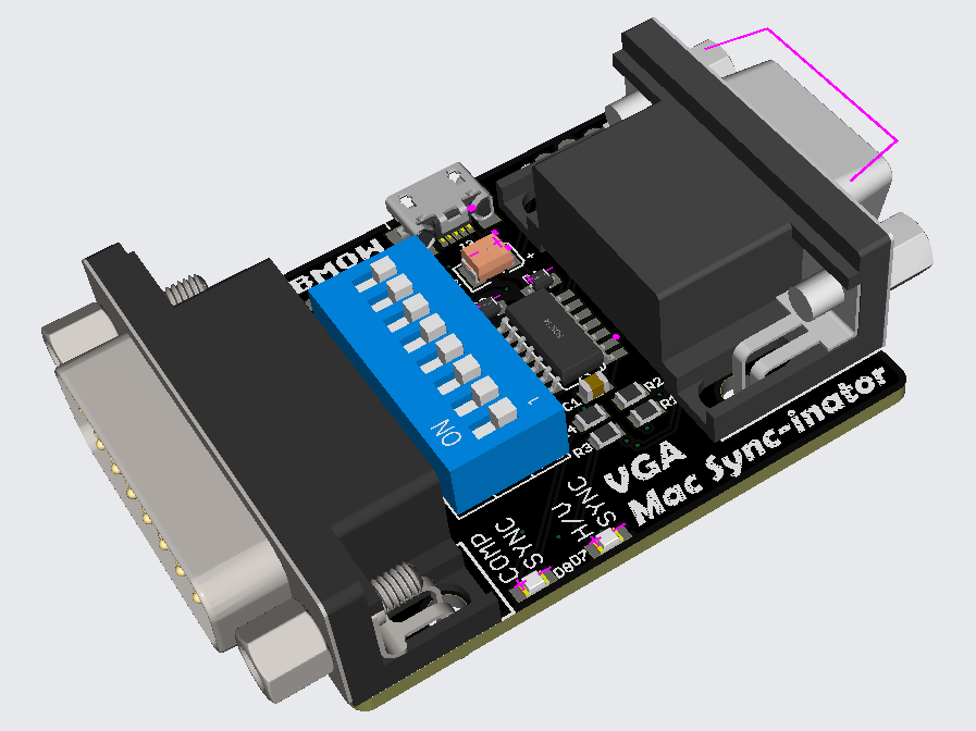
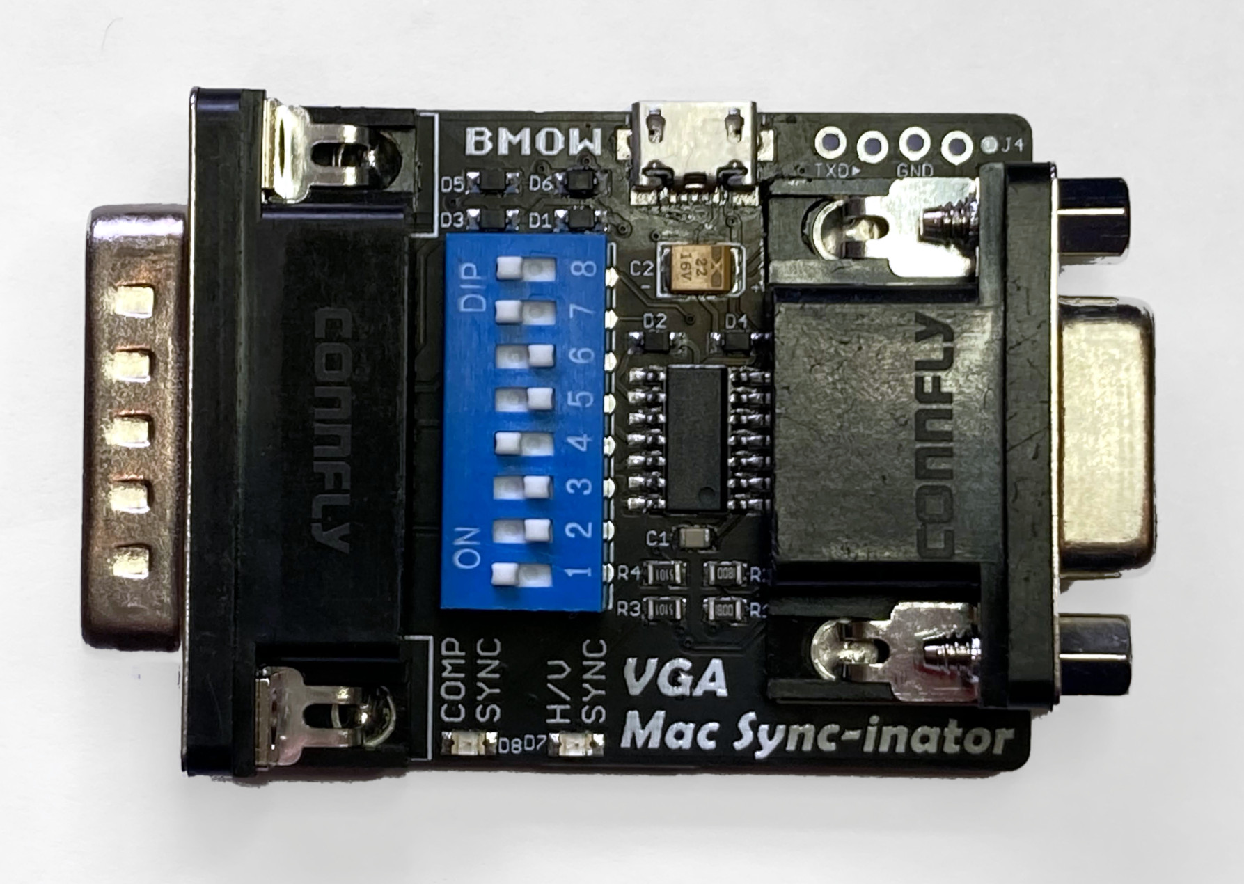
Here’s a 3D rendering of the prototype. There’s not much to the hardware: just a DB-15 for the Macintosh side, an HD-15 for the VGA side, an ATTINY404 microcontroller, and a set of DIP switches. There’s also a USB jack for an optional source of external power, although so far my tests have found it isn’t needed. A pair of LEDs light up to indicate whether the Mac is outputting composite sync, separate horizontal and vertical sync, or both. This is a valuable debugging aid when you’re staring at a black screen and aren’t sure which piece of equipment to begin troubleshooting.
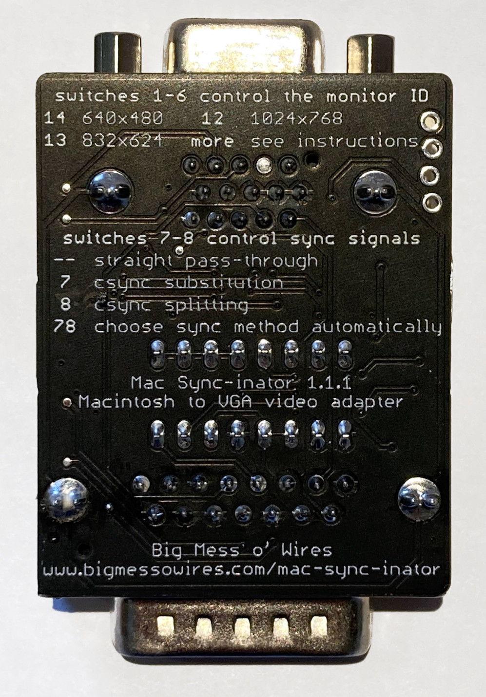
The first six DIP switches configure the monitor ID sense code that the Macintosh will see, and they function very similarly to the DIP switches on passive adapters. Many older Mac models check the sense code at startup, and use the code to determine what resolution of video output to generate, or whether to generate any video output at all. The last two DIP switches control the microcontroller’s sync conversion behavior. There are four choices:
- Pass through hsync and vsync without any conversion – For newer Mac models that already output separate hsync and vsync signals.
- Pass the Mac’s csync signal to the monitor’s hsync input – For older Mac models attached to VGA monitors that can accept a csync signal.
- Don’t pass any sync signals – For Mac models and video cards that have sync information included in the green video channel, called sync-on-green.
- Convert the csync signal into new hsync and vsync signals – For older Mac models attached to any VGA monitor, with the widest compatibility.
It’s that last option for csync conversion that’s the interesting one, and that makes this adapter unique. Passive adapters can do the first three behaviors, but not composite sync conversion.
And it works! Using the Mac-Syncinator in csync conversion mode, I’m now able to run my Macintosh IIci on any of my monitors, including the ViewSonic VG900b that has consistently been the pickiest monitor through all my development efforts. Hallelujah!
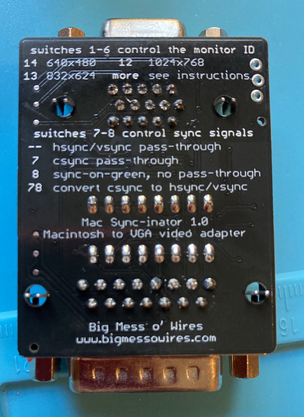
If you’ve ever used another Mac-to-VGA adapter with a set of DIP switches, then you’ve surely had the experience of not remembering what all the DIP switches do, and not being able to find the manual when you need it. It’s frustrating. To help with this problem, I’ve included a list of the switch settings for the most common video modes directly on the back of the Sync-inator:
Remaining Work
So what’s next? Is it all finished? Not quite. As of right now the Sync-inator works with the composite sync signals from the Macintosh IIci and IIsi, and from the Apple Macintosh II Monochrome Video Card 661-0518. But it doesn’t work with the Toby card (Macintosh II Video Card 820-1098) nor with a SuperMac ColorCard SE/30 that I tested. The reason is that not every composite sync signal is constructed the same way.
Here’s the csync signal from the Mac IIci, along with the new hsync and vsync signals that are created by the Sync-inator:
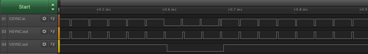
The csync signal is normally high, but there’s a short low pulse after every horizontal scan line of video. Once per frame, the polarity of the whole signal is reversed for a few lines – this inversion is the vsync. The important detail is that falling edges of csync are always regularly spaced, even during the inverted vsync period. The Sync-inator’s microcontroller uses these edges to derive timing information and create a synthetic hsync signal to feed to the monitor.
Now contrast this with the csync signal from the Apple Toby card:

During the vsync period, the csync signal polarity isn’t reversed – it’s simply flatlined at zero so there’s no timing information the microcontroller can use to generate synthetic hsync pulses. The falling edges of csync aren’t always regularly spaced either. They’re mostly consistent, but during the lines just before and just after vsync you can see the csync pulses are suddenly twice as frequent as normal.
The SuperMac card has the same flatlined zero behavior as the Toby, but not the double-speed csync pulse behavior.
The double-speed csync pulses seem like maybe they could be filtered out by ignoring any csync pulse that arrives too soon after that previous pulse. But what’s “too soon”? If I could assume a specific video resolution then I could probably use a fixed time duration for the filter, but if the video resolution might change then I probably need to measure the normal duration between pulses and then create a dynamic filter threshold based on that. Even if I knew exactly how long to make the filter, I’m not yet sure how I would implement it, since csync is triggering a hardware peripheral in the microcontroller rather than being polled and processed by generic program code.
I’ll probably focus on the flatlined zero problem first, since it’s common to both video cards. In theory the microcontroller needs to measure the average time between csync pulses, and detect cases where a csync pulse doesn’t arrive within a small error window around the expected time, and then insert a synthetic pulse in place of the missing pulse. That might be plausible if I were using a super-fast microcontroller and all of this behavior was implemented in program code, but I’m relying heavily on hardware peripherals in the chip. Those peripherals can’t necessarily be configured for that type of complex behavior. Maybe I can rig up some clever scheme of enabling and disabling interrupts at certain times, where the interrupt handlers change the hardware peripheral states, to create a behavior for a missed csync pulse. There will necessarily be timing jitter in these newly-created pulses though, plus some delay between the end of the window where csync was expected and the start of the time where the synthetic pulse is generated. From my earlier experiments, many monitors don’t react well to this kind of jitter and variance in the sync signal timing, so this whole approach may not even be viable. I guess I’ll find out.
It may be impossible to support these oddball csync formats, and I may have to footnote the Toby and ColorCard SE/30 as *not compatible with csync conversion. That wouldn’t be too bad, since the main goal was Macintosh IIci and IIsi support, which has already been achieved. But I’ll give it my best effort!
Read 15 comments and join the conversationFloppy Emu update: StuffIt file support, CD-ROM and SCSI image support, more
Vintage Macintosh fans, here’s a firmware update for the BMOW Floppy Emu disk emulator with some exciting new features that I’ve been working on for the past few weeks. Please give this version femu-231209M a try, and let me know how it works for you. Even a basic report of “it works fine, I have nothing more to say” is helpful.
StuffIt File Support via Boxing
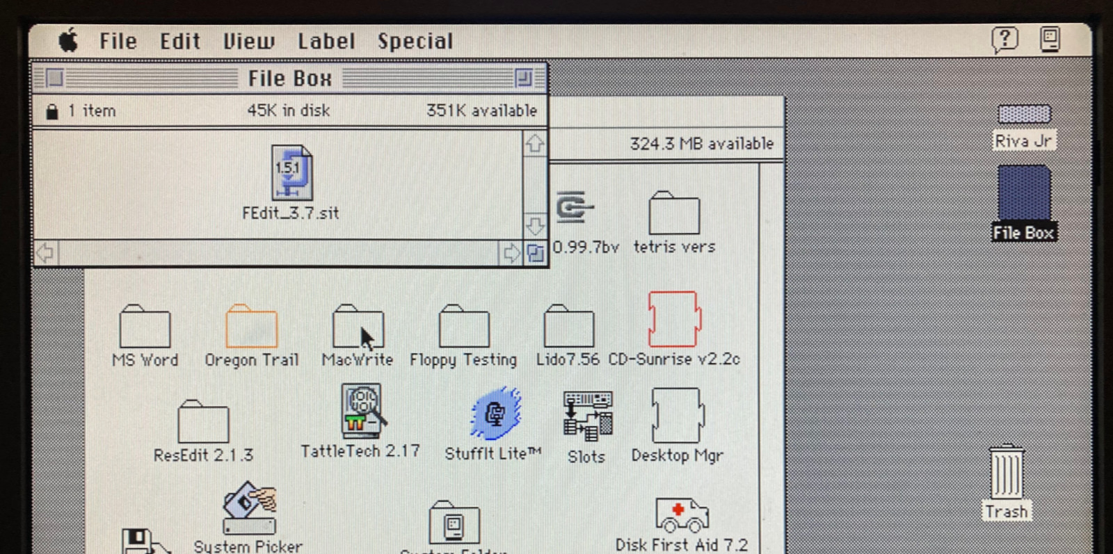
Archive files like StuffIt .sit, BinHex .hqx, MacBinary .bin, Compact Pro .cpt, and text .txt can now be directly used as if they were floppy disk images, with a new feature I’m calling “boxing”. Select a .sit file (or other archive) on your SD card, and Floppy Emu will automatically create a temporary disk image “box” that contains the file. From the user’s point of view, this basically makes StuffIt files and other archive files behave as if they were disk images, and it’s a major time-saver and quality of life improvement when you’re downloading software from The Garden and using your Floppy Emu to transfer it to your Mac.
Floppy Emu generates a read-only box disk that’s the smallest possible size to contain the StuffIt archive file: 400K, 800K, or 1440K. Your Mac will need to have support for the larger floppy disk sizes in order to transfer larger StuffIt files. 400K box disks are HFS, not MFS, so you’ll need to be running System 2 or later.
Macintosh Hard Disk support for Zulu SCSI, Blue SCSI, and CD-ROM images
For Mac models with support for HD20-type hard disks, Floppy Emu can now use disk images in SCSI device or CD-ROM formats, with an embedded Apple Partition Map, such as the disk images used with Zulu SCSI or Blue SCSI. Supported formats are HDA, IMG, ISO, CDR, DSK, and TOAST. When browsing for disk images in the Floppy Emu directory menus, these images will appear with an APM suffix, while traditional disk images will appear with an HFS suffix. For APM images, Floppy Emu will search the partition map and mount the first HFS partition in the image, ignoring driver partitions and other boring stuff.

Yes, this means Floppy Emu is now a CD-ROM emulator (sort of) – see above with a CodeWarrior CD mounted. CD-ROM images are mounted as read-only hard disks, not as removable media, and the speed is comparable to a 1x CD-ROM drive. It won’t replace a dedicated CD drive, but it’s great for installing software. If you’re running System 6, you may see an error message when using CD-ROM images complaining that the desktop file couldn’t be created because the disk is locked, just like you would with many real CD-ROMs and System 6. The INIT Desktop Manager 2.01 will fix this. With System 7 or later, it’s not needed.
Other Stuff
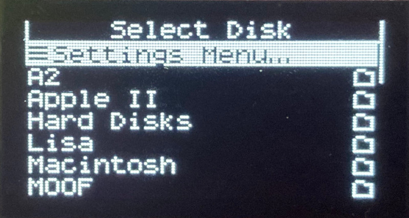
The Floppy Emu Model C also received some UI improvements and polishing. A “Settings Menu…” item has been added to the top level of the menus, providing an alternate way to return to the settings menu without needing to reset the device. The “..” directory menu item for returning to the parent directory was something that only a UNIX nerd could love, and has been replaced with “Go Back” and a curly arrow icon. Most error messages or dead-ends in the UI flow now have a way to exit or return, so it shouldn’t ever be necessary to use the RESET button to perform a hard reset of the device.

A new version of the Apple II firmware with these same UI improvements is also available. Have fun, and don’t forget to leave feedback on how it works for you!
Read 12 comments and join the conversationPower Supply Design, Group Regulation, and Vintage Computers
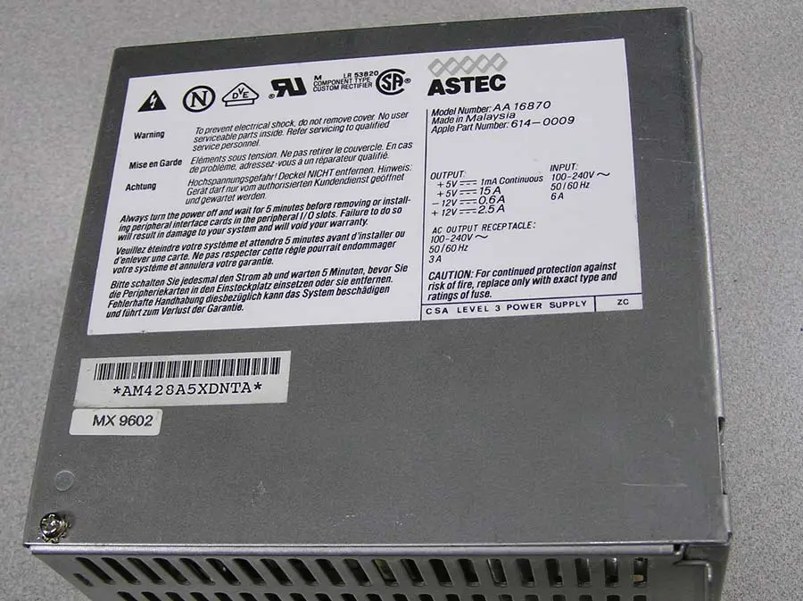
Vintage computer power supplies will eventually grow old and die. Instead of rebuilding them, many people are opting to replace them with a PC-standard ATX power supply and a physical adapter to fit the vintage machine, similar to the ATX to Macintosh 10-pin adapters I recently discussed here. But this creates a potential problem that I hadn’t originally considered: group regulation of the output voltages causing some rails to go out of spec.
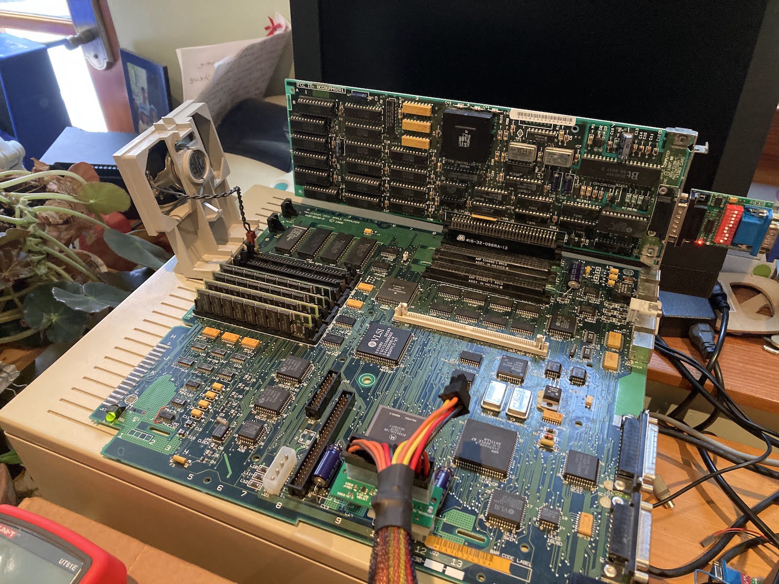
I’m trying to replace a Macintosh IIci/IIcx power supply, as shown in the photo above. With the help of a friend, I replaced it with this Logisys ATX PSU, and at first all seemed fine. But then I did some load tests in the Macintosh IIcx, adding more and more cards and peripherals while measuring the 5V and 12V supply regulation. The initial setup was a IIcx using the Logisys PSU, with 20MB RAM, no hard drives or floppy drives, no keyboard or mouse, no cards, and no ROM SIMM. I measured voltages at the empty hard drive power connector.
- initial readings: 4.932, 12.294
- +1 ethernet card, 1 ADB keyboard, 1 ADB trackball: 4.895, 12.302
- +1 Toby video card: 4.824, 12.327
- +1 Apple Hi-Resolution Display Card: 4.779, 12.340
- +2 BMOW Floppy Emus (internal and external): 4.763, 12.343
- +1 Zulu SCSI using term power: 4.742, 12.338
- +1 BMOW Wombat with attached USB hub, USB keyboard, USB mouse: 4.729, 12.343
- +1 12V fan rated 0.77W: 4.734, 12.325
Bolded values are out of spec. The additional load I was adding was all on the 5V supply, whose voltage kept sinking lower and lower while the mostly-unloaded 12V supply kept climbing higher. This is exactly what you’d expect from a PSU that uses group regulation, where all of the outputs are regulated using a single combined error feedback mechanism, instead of each output being independently regulated.
In the case of many common cheaper ATX PSUs, they are group regulated based on the combined error in the 5V and 12V outputs. In a severe cross-loading situation with lots of 5V load and minimal 12V load, the PSU is trying to split the difference by making 5V too low and 12V too high, which causes 5V to go out of spec. Adding a fan to create a small load on 12V helped a tiny bit. But extrapolating from that one fan, I’d need to add 41W of load on 12V to bring the 5V supply all the way up to where it should be.
The original stock PSU in the Macintosh IIcx and similar computers did not suffer this problem, and was presumably independently regulated. So what is the aspiring vintage computer PSU rebuilder to do here?
- Buy a much more expensive ATX PSU that is not group regulated, and that can supply enough amps on its 5V output (minimum 15A), and is small enough to fit the small physical dimensions inside the IIcx PSU enclosure. Finding options that tick all the boxes is difficult, and these may cost $100 or more. Most modern ATX PSUs can not supply enough current on their 5V output.
- Add a 12V dummy load using power resistors, something on the order of 10 to 40 Watts, to reduce the cross-loading between the 5V and 12V outputs. But what level of dummy load is correct? And what about the extra heat that will be generated?
- Design a custom PSU solution using a commercial 12V regulated supply plus a separate high-power buck converter for 5V, and another converter for -12V, and also something for 5V trickle and soft power like ATX’s PS_ON input.
- Something else clever that you may suggest.
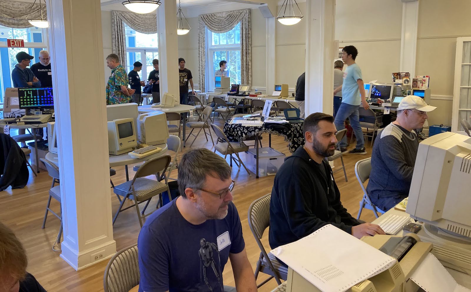
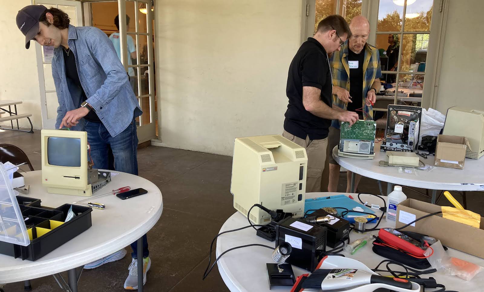
Mactoberfest Meetup Recap
The first ever Mactoberfest Meetup was a success! Everybody seemed to have a great time, and there were no serious hiccups. In a hobby that tends to be pretty insular, it was nice to spend a day with other people who share the same enthusiasm for old Apple computer stuff.
A huge thank you to the many kind and generous people who helped with setup, and later with clean-up at end of the day. I was chatting with somebody and looked up to see an assembly line of people helping stack up tables and folding chairs, without any involvement from me. Thank you to the person who helped carry many loads of trash and paper recycling to the dumpster. And especially thank you to the person who volunteered to take ALL of the remaining e-waste to a disposal facility.
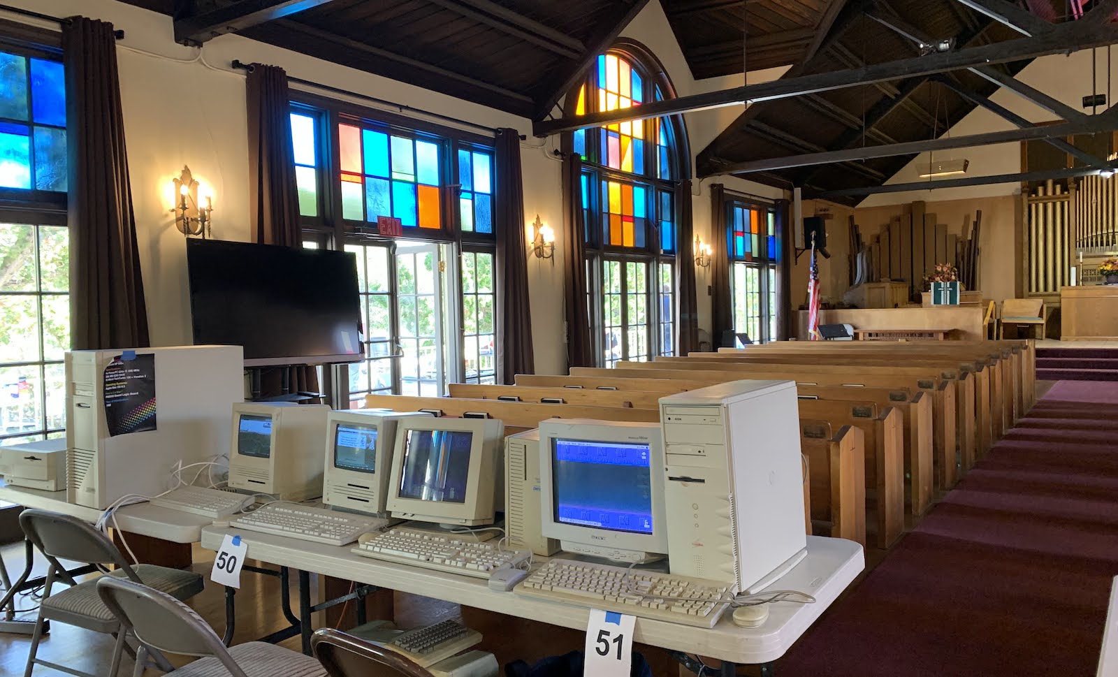
It seemed that we had exactly the right amount of space for computer displays, but I didn’t notice if some latecomers weren’t able to show all the computers they wanted to due to space limitations. Most people brought a couple of computers, but a few people had more like… 8?
About two-thirds of the computer displays were in one room, with the rest divided among two other rooms and two outdoor patios. The energy level in those other rooms seemed a bit lower, which was unfortunate but couldn’t really be helped given the venue layout. It was a very busy day.
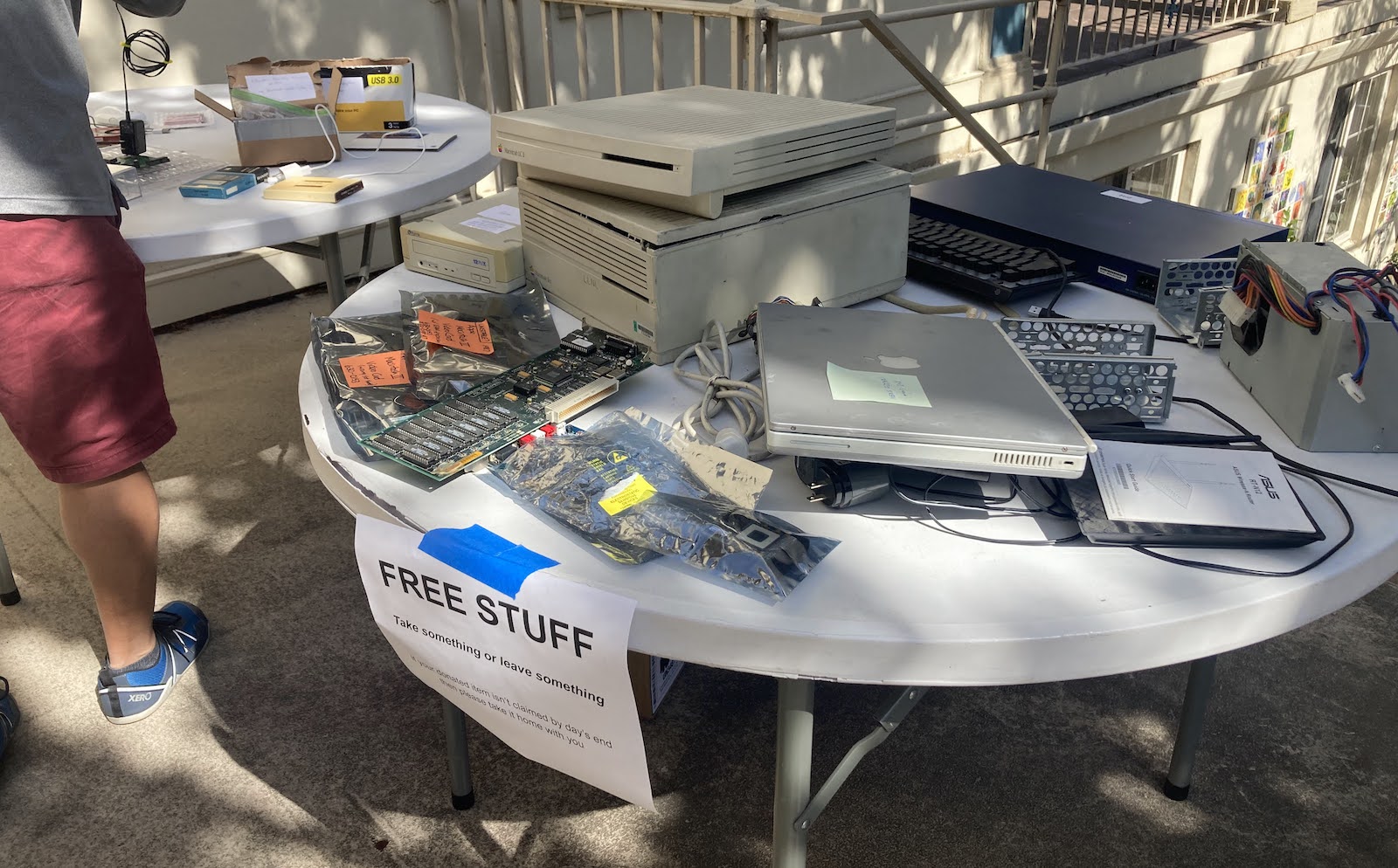
The freebies section was well-stocked, and the for sale section filled 10 tables or more. At first it seemed that there were more sellers than buyers. Very few of my own items sold during the first couple of hours, but the pace eventually picked up. For me it was more important to clean out the closets than to make a lot of money, so at 3:00 pm I took all my remaining for sale items and moved them to the freebies table. I ended up giving away several hundred dollars worth of stuff, but it all went to people who were excited to get it, and I feel good about it (except for the video card that I sold and then realized I still needed).
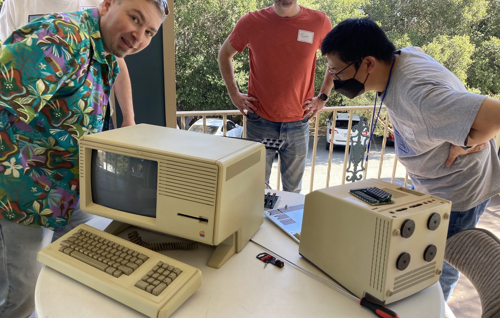
The workshop / repair section wasn’t especially busy, and I’m not sure what happened to those 35 broken machines that were listed in the RSVPs. But there was a dedicated group of about 5 people at the workshop all day. One group tried valiantly to get a broken Lisa system running again, with some partial success. And I saw somebody new to the classic Mac hobby replace a Mac 512K’s analog board to get his one-and-only Mac working for the first time, and he was super excited.
My ATX to Mac 10-pin PSU adapter kits were not very popular… I think people didn’t realize they were out there. A few people assembled a kit, but most of them came home with me again.
We had no problems at all with fuses or the building power, except for one breaker that repeatedly tripped whenever my soldering iron was plugged in. We eventually traced this problem to a damaged extension cord.
The Tetris Max competition was won in dramatic fashion, with the high-scoring game coming in the final moments of the contest. The winning score was 18832 and the winner took home a Performa 460 system as his prize. I will admit the level of Tetris Max competition wasn’t quite up to the level that I’d hoped and most people who competed were spectacularly bad at the game! There were a shocking number of people who had never played tetris before. But it was all good fun.
The day was chock-full of interesting people and interesting stuff. We did get at least one of the original Macintosh developers in attendance. And the variety of computer displays was staggering. I regret that I didn’t have time to see everything or talk to everyone, but some of the highlights were:
- a PC sidecar for compact Macs, with dual 5.25 inch drives
- an enormous Daystar Genesis MP Quad-604e system
- an extensive collection of Dog Cow items
- a set of tiny displays with integrated microcontrollers that directly run After Dark screensaver code resources
- an RP2040 digitizer-upscaler-VGA converter for compact Mac video output
- a Mac SE logic board in a very nice custom display case, with modern power and video
- Yamaha audio card for Apple II, and a custom-made stand alone audio synth
- a newly-made Hypercard disk zine
- a collection of Colby Macs
- tons more stuff that I’m too tired to describe
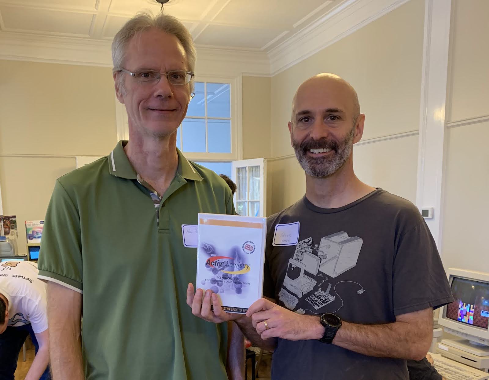
A personal highlight for me was reconnecting with an old friend with whom I’d worked on a piece of commercial Mac software released way back in 1997. Here we are posing with a copy – still in the original shrink wrap!
Throughout Mactoberfest, what really struck me was how much the hobby of “Macintosh collecting” has changed since I first got involved about 12 years ago. Back then, it seemed that Macintosh collecting was just exactly that – collecting machines, fixing broken ones, and playing with software. But over the years collecting has merged with the DIY / maker community, so there’s now this explosion of NEW hardware and accessories for these old computers. A huge number of people at the Meetup were using modern gadgets, not just my Floppy Emu but also SCSI emulatiors, video digitizers, power supply replacements, CPU replacements, microcontrollers and Raspberry Pis spilling out of every open computer port. There are just so many exciting new hardware development projects going on.
The only part of Mactoberfest Meetup that wasn’t great was the hard split between interactive computer displays and the for-sale section of the meetup. This was forced by the building layout and the relative scarcity of electric outlets, because there simply wasn’t enough space adjacent to electricity for both at once. But it created a weird dynamic where the flea market had interested buyers who couldn’t easily find the sellers to ask questions or to buy stuff. I’m sure this led to fewer sales overall.
There was also a strange dichotomy between people who brought computers to show off and people who showed up empty-handed to look around. During the advance planning I sometimes felt like I had to twist people’s arms into agreeing to bring their computers, and most people would have preferred to simply look around, in which case we would have had 100 lookers and nothing to look at.
Overall it was a great day and there was lots of talk about “next year” and offers to help. I’ll take some time before giving any thought to what might happen in 2024, but it’s clear there’s plenty of local enthusiasm and interest for something like this to be a regular event. I’ve only been to one VCF show, so I’m not a great person to compare them, but I would say that Mactoberfest had a less organized, less formal vibe. It was just people hauling out whatever machines were in their closets to share their hobby with other folks, mess around, and have some fun.
So will there be a next year? Aside from the financial cost and all the work that went into planning, my biggest concern is liability. It’s nice to think that “everybody here is cool, nothing bad will happen” but that’s head-in-the-sand mentality. Imagine if somebody had fallen on the slippery steps while carrying in a heavy computer, or a miswired electrical outlet had fried somebody’s $10000 Lisa system, or somebody walked out the front door with a stolen computer that wasn’t noticed until later, or a kid burned himself with the soldering iron, or the hot air tool got knocked on the floor and set the drapes on fire. I wouldn’t want to lead Mactoberfest again by myself, but maybe we could put together a team of people to research insurance options and planning requirements, and make something happen next year.
Thank you to everyone who attended, it was great to meet you all!
Read 5 comments and join the conversation