

Case Packing Time Lapse Video
Frosted Ice cases for Floppy Emu are back in stock at the BMOW store, and I took the opportunity to make a time lapse video of the case packing process. Where does all the time go? Last week’s video featured the behind-the-scenes order fulfillment process, in which pre-bagged case kits were already prepared. Today’s video shows where those came from.
The plastic case parts come pre-made on large laser-cut sheets from a third party, with enough parts for seven cases per sheet. The parts must be pulled out, sorted, and placed into individual bags. Fastener hardware is added to each bag, before it’s sealed and ready for sale. Extra light pipes from clear sheets are saved to be reused with opaque sheets for Snow White cases. It’s one more unglamorous task that consumes surprising amounts of time.
Things to find in the video: Macintosh Family Hardware Reference guide, Imagewriter II printer.
Read 2 comments and join the conversationReflow Soldering Fail
I’ve long wanted to try reflow soldering of surface mount components, using solder paste and hot air or a hot skillet, and I recently had an opportunity to try. Unfortunately the results were very poor, and I was left wondering what I did wrong. Compared to my normal method of drag-soldering surface mount chips with a standard iron and liberal amounts of flux, the reflow method with solder paste took more than twice as long and led to worse results overall.
My test case was the ROM-inator II SIMM, which has a couple of chips with a 0.5 mm pin spacing. With my normal soldering iron, I can tack down a few corner pins, drag solder the rest of the pins, and then use desoldering braid to clean up the inevitable solder bridges that sometimes occur between adjacent pins. It’s something of a slow and tedious method, but it works.
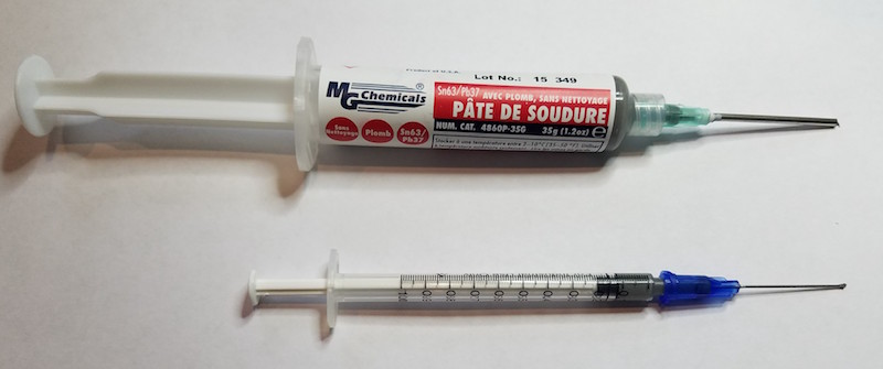
For this reflow experiment, I used a syringe of MG Chemicals Leaded Solder Paste. The needle on the MG syringe is quite large, and the bead of solder paste it dispenses is far too wide for detailed surface mount work. I dispensed about 0.1 mL of the solder paste into a second 1 mL syringe with a 22 gauge needle, which allowed me to create a nice narrow line of paste with very little finger pressure on the syringe’s plunger.
Solder paste has a limited shelf life, and you’re supposed to keep it refrigerated to help preserve it. I believe the flux in the solder paste evaporates more slowly at low temperatures. I made a conscious choice not to refrigerate, accepting that the paste would spoil faster than normal, because I wasn’t excited about keeping leaded solder where I keep my food. For this test, the solder paste was just one week old, and should still have been quite fresh.
I didn’t use a PCB stencil, because I didn’t have one, and because I was skeptical I could hand-position a stencil to sub-millimeter accuracy anyway. I also wasn’t excited about the mess created by squeegeeing solder paste across a stencil. Instead, following some advice from a tutorial, I used the syringe to dispense a very narrow bead of solder paste straight down the line of pads on the PCB. While it might seem that this would cause all the pins to be soldered to their neighbors instead of to the pads, the magic of flux and solder surface tension should have made it work OK.
Using tweezers, I positioned the chips on the pads, aligning them as accurately as I could. The MG solder paste had a nice amount of stickiness to it, holding each chip steadily in place after I’d positioned it. That magic surface tension of solder should have helped here too, causing the chip to “snap” into perfect alignment with the pads once the solder began to melt.
I used a hot air rework station to heat the pads, and before long the solder paste melted into a silvery and shiny color. I let it go for a few more seconds to ensure everything was fully melted, then removed the hot air and let the board cool.
Results
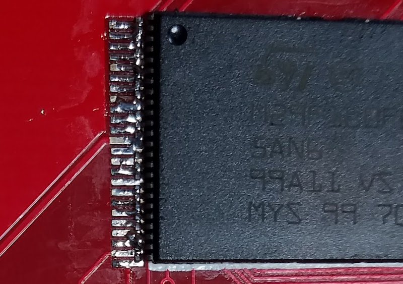
Despite having put down a very narrow bead of paste, many of the pins were bridged together. In this respect it was as bad or worse than my hand-soldering efforts, which was disappointing. But while some pins became bridged to their neighbors, other pins had too little solder, or looked completely dry. Overall I’d say the row of pins looked like it had too little solder rather than too much, so I don’t think the bridged pins were due to applying too large a bead of solder paste.
A second and more serious problem was the positioning of the chip. When hand soldering with an iron I can usually align those 0.5 mm pins with their pads fairly accurately, but the gray solder paste made the task more difficult this time. After dispensing the solder paste and placing the chip, but before melting the solder, the row of pins looked like a silver and gray blur. It was very tough to see if it was positioned accurately. The result was that two of my chips were positioned with the pins misaligned far enough from the pads to create a mess I was never able to fix. It only takes about 0.2 mm of misalignment to create a major problem with pins this closely spaced.
Even when the chips were aligned properly, I still had to go back and forth over each row of pins with the iron and flux, to fix the solder bridges and flow more solder onto pads that had too little. In effect, I had to drag solder the chip after having already reflow soldered it. Definitely not an improvement over the old method.
I built four ROM-inator II SIMMS this way, refining my technique each time in the hopes that the results would improve, but they never really did. Two of the four SIMMs couldn’t be salvaged, and had to be scrapped.
The title photo above shows one of those reject SIMMs, with a poorly aligned chip, after I’d made about 50 passes with an iron, flux, and desoldering braid trying to clean it up. It’s a mess, which is why I like the photo, but don’t take the photo as being a literal example of the results immediately after reflowing. I should have thought to take some photos after the reflow process, but before I’d touched any pins with an iron. It looked much cleaner and nicer then, but was misaligned and had many solder bridges and many pads with low or no visible solder.
Explanation
Why did this work so poorly? I don’t think it was the absence of a stencil. Attempting to position the chip smeared the solder paste around, so even if I’d had a stencil and used it perfectly, I still would have had smeared paste between the pads anyway.
I also don’t think my hand-dispensed solder paste bead was the problem. Using the 1 mL syringe, I was able to dispense a nice and even bead that was about as wide as a single pad, roughly 0.3 mm or so. Given the occasional low- and no-solder pads I observed, I probably had too little solder if anything, not too much.
Maybe 0.5 mm spaced pins are simply too small and close to be reflow soldered using this method? For comparison, I used the same reflow method to solder some 0805 sized SMD capacitors on this PCB, and it worked perfectly every time. No doubt larger sized components are easier to solder correctly, but I’m dubious that 0.5 mm pin spacing is beyond some threshold that can’t be reflow soldered using this method.
Maybe the temperature profile during reflow was far enough off to cause major problems? A real reflow process in a commercial oven would have a preheat phase about 4 minutes long, then an actual reflow time (above the solder’s melting point) of 60-90 seconds. My hot air method was much faster than that: point the hot air tool at the pads, wait maybe ~30 seconds for the solder paste to melt, wait another ~10 seconds to make sure it’s completely melted and reflowed everywhere, then remove the hot air.
Maybe the solder paste had already gone bad after a week at room temperature. That seems hard to believe, but it would explain the apparently poor wetting that I observed, with frequent solder bridges at the same time as other pins were dry, and the failure of the chip to snap into the proper alignment when the solder melted. The MG Chemicals syringe doesn’t have a date on it, but it’s marked with lot code 15-349 and was purchased new last week. If 15-349 means it was made in 2015 (on the 349th day perhaps), and the syringe has been stored at room temperature in an Amazon warehouse since then, that would certainly be a problem.
Maybe the way I heated the pads with the hot air gun caused a problem? This seems plausible. The heat was localized to a small area, so I would reflow the pins on one side of the chip, then reflow the other side 20 seconds later. Perhaps if the entire PCB had reached reflow temperature at the same time, using an oven or skillet, I might have had better results.
Any other good theories?
Read 12 comments and join the conversationHobby Business Time-Lapse Video
This time-lapse video shows all the steps needed to fill six typical BMOW hardware orders. Running an electronics hobby business can be lots of fun, but can also be highly time-consuming. If your operation is too small to support other employees, you’ll spend the bulk of your time prepping product and stuffing boxes instead of developing new tech.
What exactly is involved in filling somebody’s order for a new gadget? Even when the products involved are pre-assembled and “ready to ship”, there’s still work to do. Starting from the beginning of the video, here’s the chronology:
0 minutes – Download the recent order data, and print packing lists. Make a little pile on the floor for each outgoing order. Add quickstart guides and instruction sheets to the piles, as needed.
4 minutes – Pull the LCD off each Floppy Emu, and tighten its mounting tabs. Adjust the LCD contrast to something reasonable – the exact level varies from one LCD to the next. Flash the newest Emu firmware to the board.
12 minutes – Grab a set of DB19 adapters and a bundle of ribbon cables. Remove the DB19 adapters from their anti-static bags, and put the Emu boards in the bags. Connect the cable assemblies, fold them up neatly, and add everything to the growing piles on the floor.
16 minutes – Cut the SD memory cards from their cardboard packaging. Copy the master image to the cards, using a stand-alone SD duplicator. Add to the piles. Also start wrapping some items, during the copying dead time.
22 minutes – Add enclosures to the piles. The enclosure parts were bagged previously, in a separate time-consuming process of punching and sorting parts from laser-cut sheets.
23 minutes – Pack fragile items in bubble wrap. Fold up the papers.
28 minutes – Buy necessary postage. Custom software determines what postage type and amount is needed for each shipment.
29 minutes – Why is this Japanese address getting rejected by the address validator? Manually rewrite the address, twice.
33 minutes – Print the postage.
36 minutes – Pack the finished piles into boxes or padded envelopes. Seal them and affix the postage.
42 minutes – Put some tiny spare parts into an envelope. Hand-address the envelope to the customer.
46 minutes – Collect all the outgoing mail into a bag, and clean up the leftover scraps.
The entire process in the video takes 47 minutes, which excludes the time needed to deliver the packages to the post office. All tolled, it’s about an hour of time.
If you’ve ever run a small hobby business, you’re probably nodding your head at all of this. If you’re thinking about turning your hobby creations into a small business, I don’t want to discourage you, but the reality is that selling physical goods takes time. It’s fun tinkering with interesting electronics, and talking with like-minded people, but the mundane work of getting parts and filling orders consumes most of the time you can devote to the business. Developing iPhone apps is probably a smarter way to earn extra dollars!
Bonus game: Search the video to see how many geeky electronics items you can identify hidden around the room.
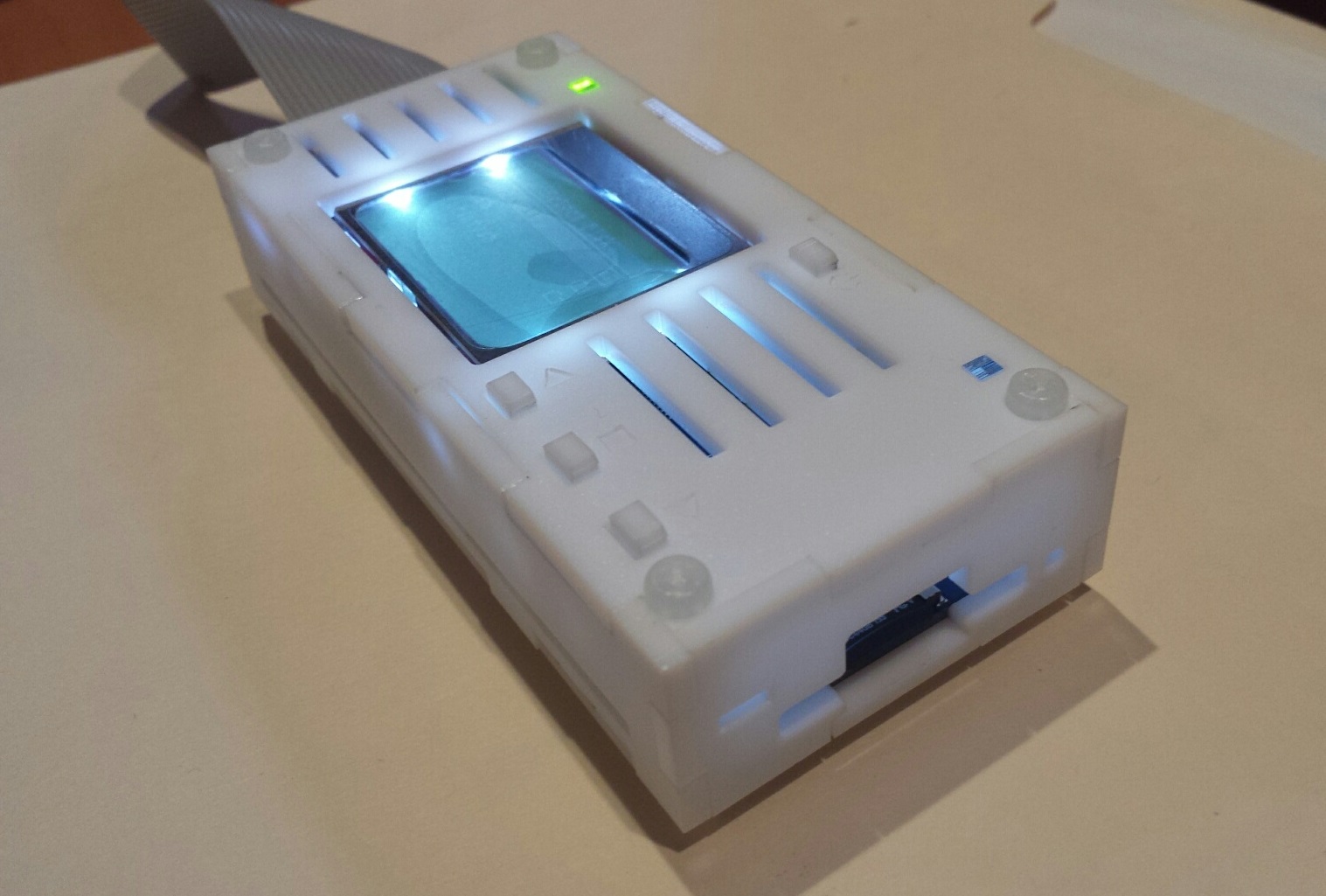
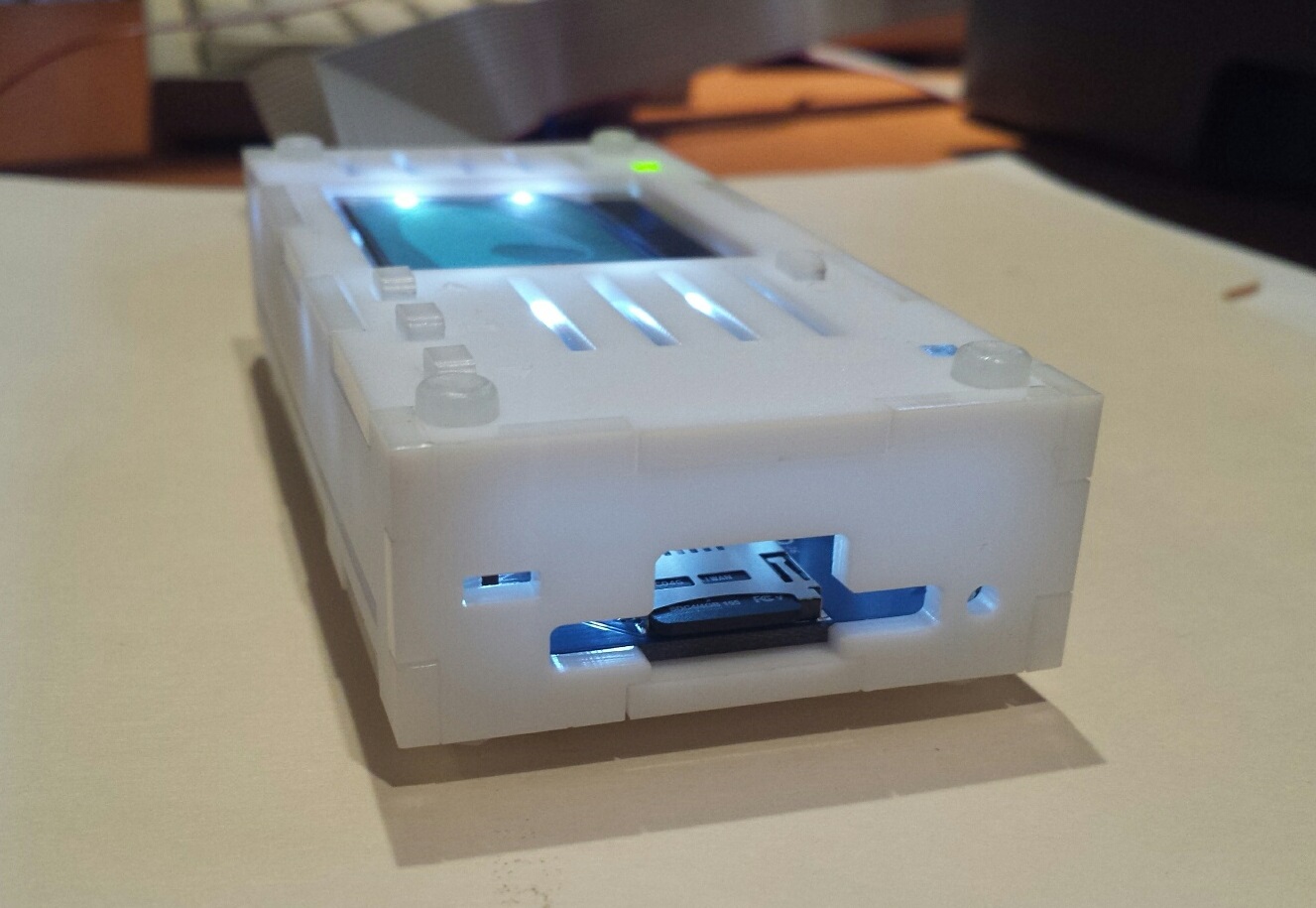
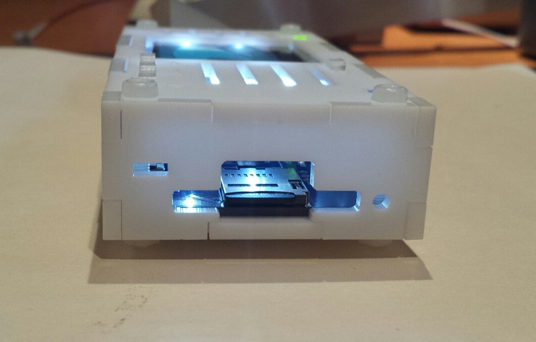
Read 4 comments and join the conversationNow Available – New Enclosure Styles
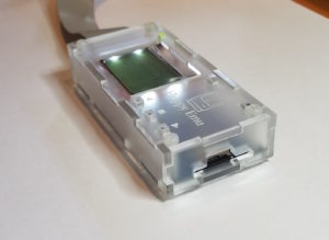
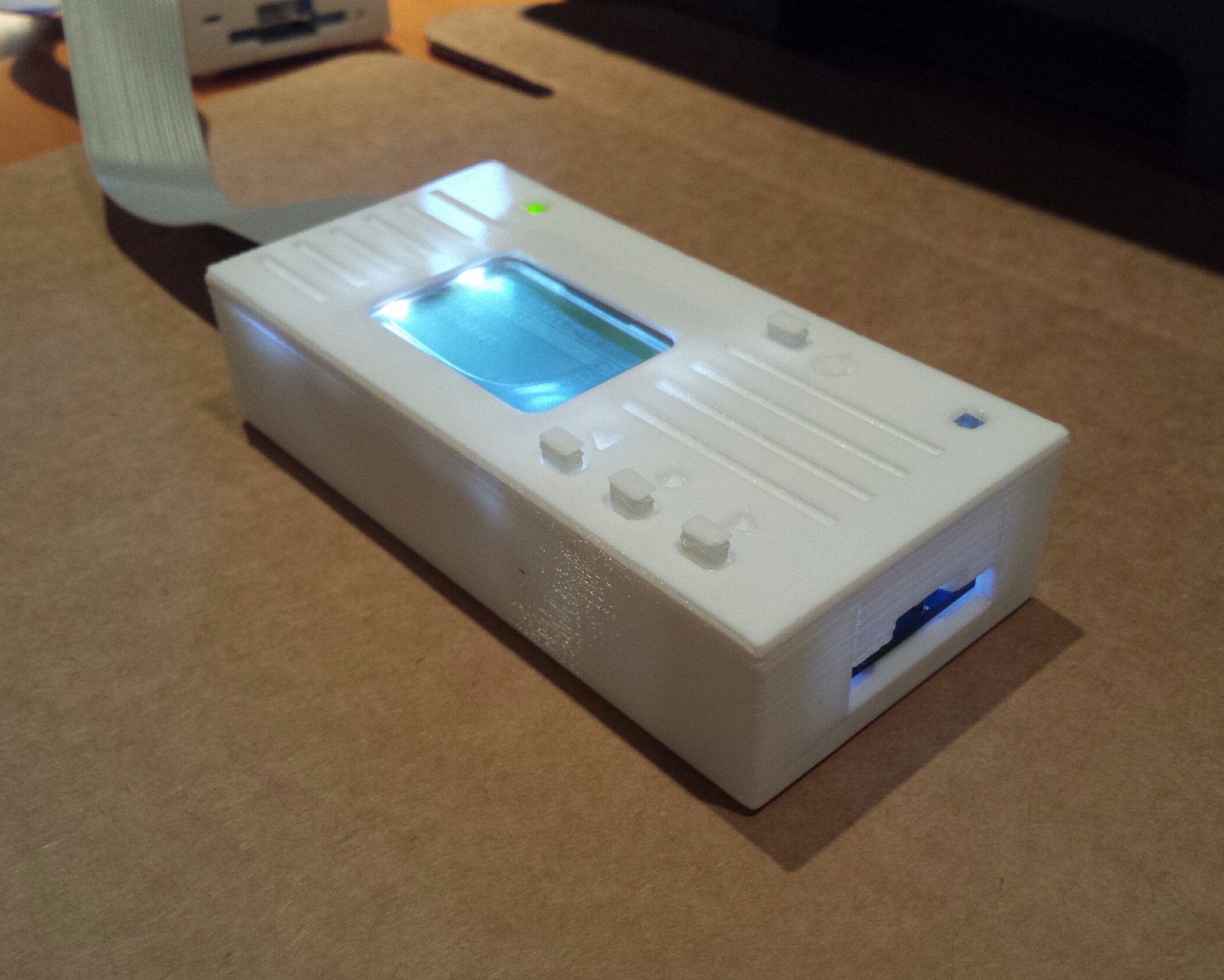
After several months of experiments and refinements, two new enclosure styles for Floppy Emu are finally available for sale. First up is a Snow White case with the looks of a miniature external floppy drive. The grooved white laser-cut case mimics Apple’s vintage Snow White design style, made famous by machines like the Apple IIc. This case uses a matte finished acrylic that’s slightly textured, and will look at home alongside your other retro computer hardware. The buttons in bright blue provide an attractive visual contrast, adding an extra touch of class.
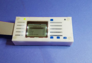
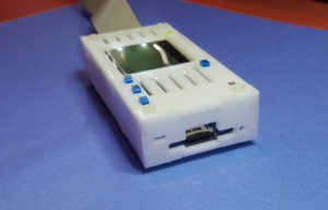
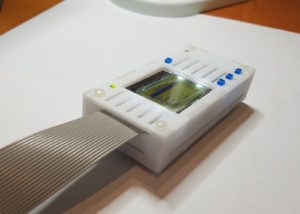
The second new style is frosted ice, and it’s replacing clear acrylic as the default case style for the deluxe bundle. The frosted ice case has a matte finish that resists fingerprints, and allows some light through without being totally transparent. It retains the “happy computer” etched logo from the earlier case style. Frosted ice has a retro-futuristic vibe like a 1960’s sci-fi drama. Danger Will Robinson!
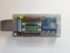
Both new case designs incorporate a small but significant change to the button stalks, which are 0.3 mm taller than before. This should help minimize button slippage caused by variations in the acrylic material thickness.
You can find the new cases in the BMOW Store.
Read 2 comments and join the conversationSnow White Case Experiments
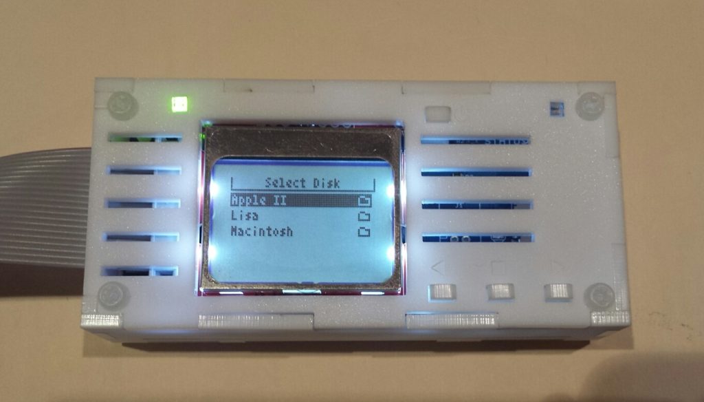
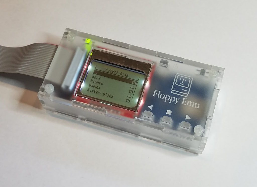
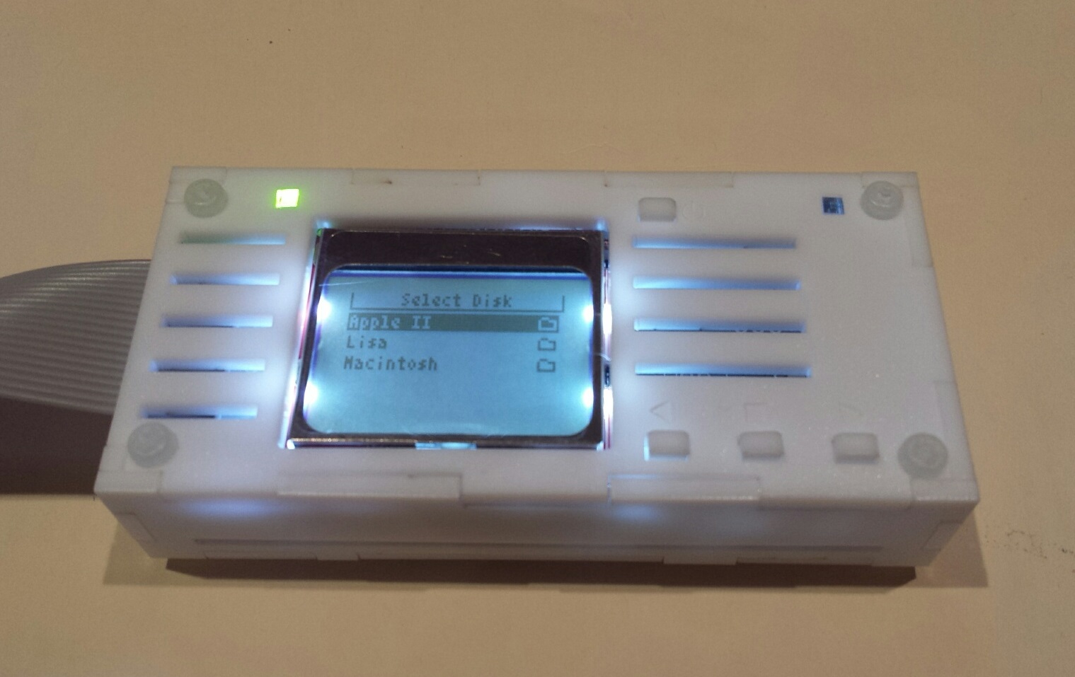
It’s been a few months since I experimented with some alternative laser-cut and 3D printed case designs for the Floppy Emu disk emulator. The most popular case concept was the Snow White design, intended to complement the design style and color of mid-1980’s Apple computers. I’ve continued to experiment with the Snow White design as time permitted, and have finally arrived at a laser-cut Snow White case that I’m mostly happy with.
The laser-cut case is constructed from the same matte white acrylic that I used in the last prototype, which is about as close to vintage Apple coloring as I can get. But instead of subtle engraving for the case lines and other details, they’re now cut-outs that go all the way through. It’s hard to see in the photos, but the matte acrylic also has a slight texture to it. This creates a look that’s quite different from the smooth gloss normally associated with acrylic. I like it a lot.
With this prototype, I also tweaked the button plunger size very slightly, which should help give the buttons a tighter feel.
A question to readers: What do you think about the single grooves on the lower part of the sides? Good or bad? I was trying to echo the design of the top plate’s lines, but I’m not sure if plain solid sides would be better.

Working with a friend, I also did a few more experiments with 3D printed cases. These look attractive and are quick to assemble, but I concluded they’re just too slow and expensive to manufacture. I won’t be making any more 3D printed cases, but the remaining 3D printed prototype cases are available for sale if anyone would like one.
My goal is to create a polished Snow White case option that I can offer as an alternative for people who prefer this style. Meanwhile, I’m also working on some refinements to the standard case… more on that soon!
Read 3 comments and join the conversationNew Firmware for Floppy Emu
After a long period of hibernation, today I’ve released a set of firmware updates for the Floppy Emu disk emulator. These updates provide a few user interface improvements taken from customer suggestions over the past year, and also fix a couple of small bugs. Enjoy!
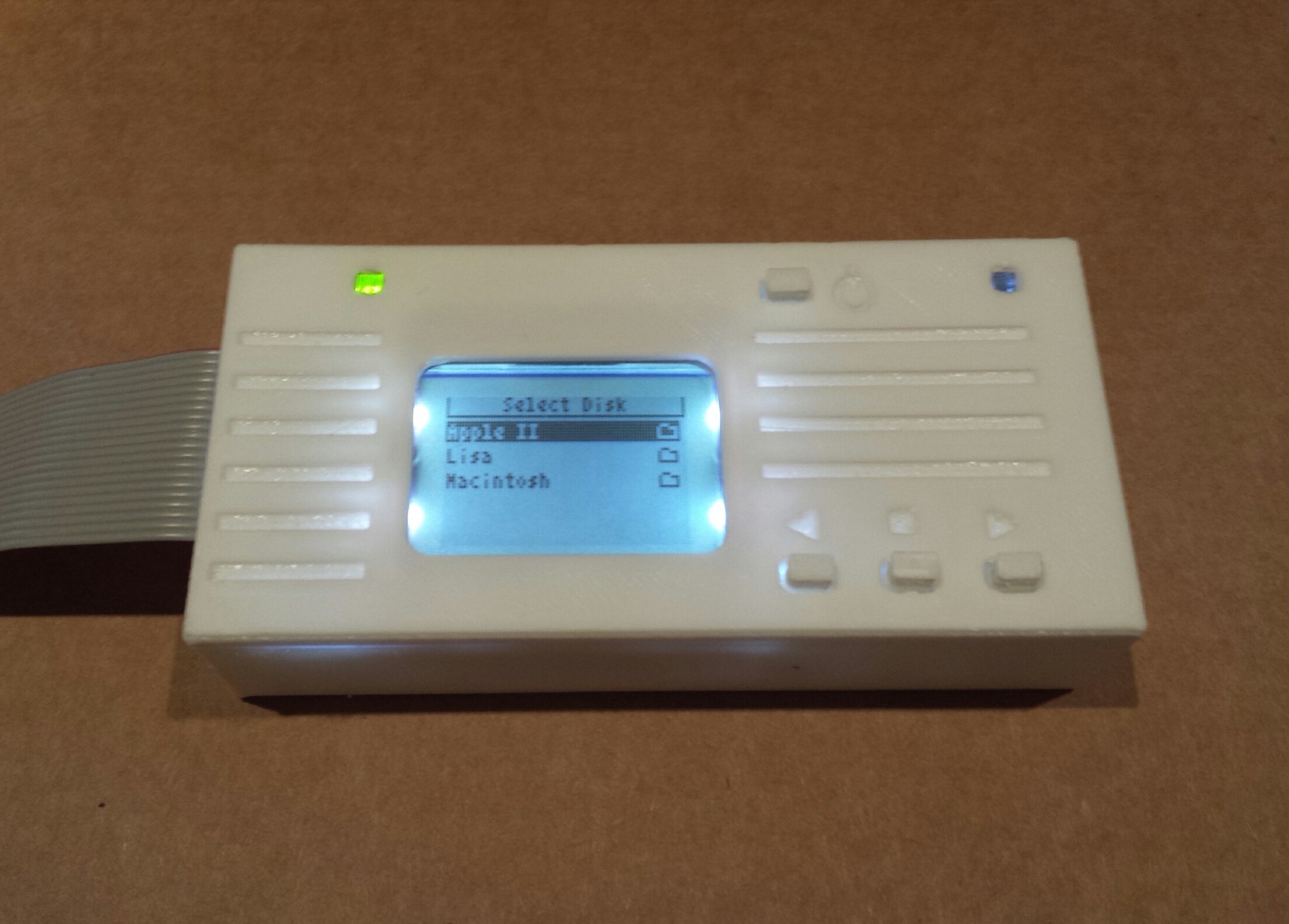
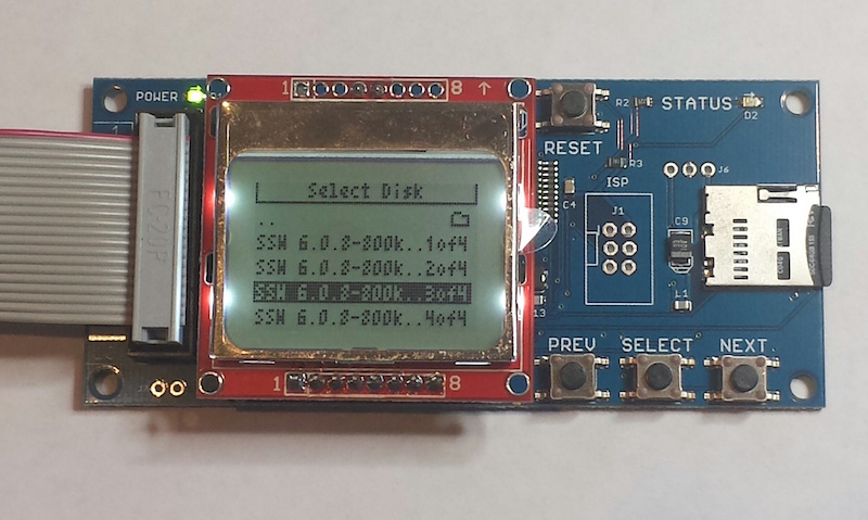
Ellipses in Long File Names – Don’t you hate it when you’ve got several disk images with very similar names, like Operating System Install Disk 1.dsk, Operating System Install Disk 2.dsk, and Operating System Install Disk 3.dsk? On the Floppy Emu’s built-in display, while browsing the contents of your SD card, the end of those long filenames were all cut off. You couldn’t tell which one was which when selecting a disk image from the menu. With today’s firmware update, the middle of those long filenames will now be replaced with an ellipsis, retaining the beginning and end of the name. Several people have been asking me for this feature for at least a year, so here you go.
Obvious Errors for Unsupported Disk Image Types – The Floppy Emu is always running in a specific emulation mode, like Apple II 5.25 Inch mode or Macintosh HD20 Hard Disk mode. When you’re browsing the contents of your SD card, the Emu knows which disk images are supported by the current mode, and which aren’t. The old behavior was to only display supported disk images and hide the others, but this seems to have confused everybody and left them wondering why their files disappeared. The new behavior is to list (mostly) all the files on the SD card, then show an error if the user selects something that isn’t a disk image supported by the current mode. In this case, you’ll see “disk image type is not supported in the current emu mode”.
Emulation Mode Highlight – Speaking of emulation modes, many people didn’t seem to realize that they exist, resulting in confusion when using the wrong mode or not knowing how to change modes. I can ask them to RTFM, but it would be nice if the UI made it more obvious. I’ve changed the Emu’s startup screen to display the current emulation mode right at the top, in inverse text, so hopefully it will now be impossible to overlook. I also fixed a subtle problem that affected people who switched from the Apple II firmware to the Mac/Lisa firmware: the Emu was defaulting to Lisa 3.5 Floppy mode after the firmware update. Quite a few people didn’t notice, and then couldn’t understand why floppy emulation didn’t work with their Macintosh. I’ve changed the behavior so it will now default to Macintosh 3.5 Floppy mode after the firmware update.
Get the new firmware here:
Macintosh and Lisa, for all Floppy Emu models: hd20-0.7G-F14.5
Apple II firmware, for Floppy Emu Model B: apple-ii-0.1R-F8
Apple II firmware, for Floppy Emu Model A: apple-ii-0.1R-F6
With any firmware update, there’s always a chance that I’ll accidentally break something, so please give me your feedback on whether these new versions work for you.
Read 9 comments and join the conversation