

Archive for November, 2014
Reverse Engineering the HD20
Finally after nine months, a progress update on HD20 emulation! Back in February I wrote about my efforts to reverse engineer the Apple HD20, an external 20 MB hard drive for the Macintosh that was introduced way back in 1985. This was before the introduction of SCSI support, so the HD20 connected via the Mac’s floppy port. With luck, that might make it possible to emulate an HD20 using the hardware I previously developed for Floppy Emu, the Macintosh floppy drive emulator. 20 MB (or more?) of external storage for a Mac Plus or other vintage machine, stored on an SD memory card, with no dependencies on SCSI or aging rotational disks! But doing it would require understanding how the HD20 worked well enough to emulate it.
A Little History
The HD20 has a famously strange reputation. Despite sharing the same DB-19 connector as a floppy drive, it used an entirely different communication protocol. When SCSI support was introduced in 1986, external hard drive solutions quickly adopted the new standard, so the HD20 was the only hard drive to ever use this protocol. The protocol was never documented anywhere publicly, and eventually became an old, obscure mystery. Emulating the HD20 was virtually impossible.
Then about a year ago, a couple of ancient Apple internal documents about “directly connected disks” surfaced on the internet. The term “HD20” didn’t appear anywhere in them, but it was clear that’s what they were about. Two docs dated March 1985 and May 1985 outlined the DCD communication protocol. They described a state-based command-and-response system, in which data was transferred in groups of 7 logical bytes encoded into 8 physical bytes. But the docs conflicted with each other in many details, and were silent on other critical points. And as I later discovered, both docs conflicted with tests performed on a real Macintosh system. Still, it was enough to get started. In my February experiments, I got as far as fooling the Mac into believing an HD20 was connected, and receiving/decoding a drive status query. But I was never able to send back a reply, and I eventually lost interest.
New Preparations
Thanks to a slow trickle of people who kept encouraging me to look at it, I recently dusted off the HD20 project again. I could receiving a drive status query, but how could I send a reply? What kind of handshaking was needed to tell the Mac a reply was ready? How big was the reply, and what data did it contain? What checksum method did it use? Armed with the DCD docs and some educated guesses, I programmed the Emu hardware to send a drive status response. Then to test it, I wrote a Macintosh program to read arbitrary sectors from disk ID #2, the first connected DCD.
Side note: it’s not a simple thing to write new software for a 30-year-old computer system! In order to create my test program, I used an old copy of Metrowerks Codewarrior, running under emulation in Basilisk II. The finished program was saved to Basilisk’s virtual hard disk image. Then I mounted a virtual floppy disk image in Basilisk, and copied the program to it. After quitting Basilisk, I copied the floppy disk image file to an SD card, put the SD card in a second Floppy Emu (the first one having been turned into an HD20 Emu), booted my Mac Plus with the Floppy Emu attached, mounted the floppy image, and copied the program file to the Plus’s external SCSI disk. Oof!
The Mac really doesn’t like to boot if it thinks there’s a sort-of-working HD20 attached. It either hangs for long periods, or complains endlessly about disk errors. If I used the SCSI drive and managed to boot into the Finder, the Finder would freeze forever while trying to communicate with the emulated HD20, so I could never actually launch my test program. Doh! My solution was to configure the Mac to run the test program immediately at boot-up, instead of running the Finder. With the not-really-an-HD20 disconnected, this can be done by highlighting the test program, then selecting the Finder’s Special -> Set Startup menu.
Crawling towards Two-Way Communication
At last I had something to test, and of course it didn’t work. The test program reported error -17, which according to Inside Macintosh means “driver can’t respond to this control call.” I could tell my hardware was receiving the drive status command, and trying to send a reply, but beyond that I was blind. Did the Mac receive the reply, but reject it as misformatted? Was it the wrong size, or encoded incorrectly? Maybe the handshaking wasn’t working, and the Mac wasn’t even seeing any response at all? No matter what I did or what I tried, all I got was error -17, with no further clues to help me troubleshoot.
From another Apple document, I knew there were supposed to be HD20-specific error codes, and I could see places in the Mac ROM disassembly where those errors were generated. They are:
; New HD20 error codes

wrtHsLw         equ     $10             ; HSHK low before starting
wrtHSLwTO       equ     $11             ; Time out waiting for HSHK to go low
wrtHSHighTO     equ     $13             ; Time out waiting for HSHK to go high
rdHsHi          equ     $20             ; HSHK high before starting
rdSyncTO        equ     $21             ; Time out waiting for sync ($AA) bye
rdGroupTO       equ     $22             ; Time out waiting for group
rdHoffSyncTO    equ     $24             ; Time out waiting for sync after holdoff
rdHsHiTO        equ     $25             ; Time out waiting for HSHK high
rdChksumErr     equ     $26             ; Checksum error on response packet
invalidResp     equ     $30             ; First byte in response packet was wrong
sqncNumErr      equ     $31             ; Sequence number in response packet was wrong
dNumberErr      equ     $32             ; Drive number in response packet was wrong
noResp          equ     $40             ; No response packet ever received
Those are some great low-level error codes covering handshaking, checksums, and other details. Why was I only getting error -17, instead of the more detailed codes? With no useful feedback, I continued pounding away at the problem blindly for far longer than I should have, but got nowhere.
Something was generating that -17, and I was determined to find out what. On the early Macs, most of the operating system code is stored in ROM, and this includes the HD20 I/O routines. It’s possible to pull those ROMs, dump the data from them, and run it through a 68000 disassembler. Other people have done this long ago. But the result is only useful to a point – it’s just raw assembly language code, without any symbolic names or comments or any other context to help understand what it’s doing. Just thousands of lines like these:
SubA.L    A4, A4
SubA.L    A5, A5
MoveQ.L   $1, D3
MoveQ.L   $0, D6
MoveQ.L   $0, D7
Move      $64, $1C0(A1)
Move      $4650, $1C2(A1)
Cmp.B     $3, $19C(A1)
BNE       L4809
Move.L    $14C, D7
Move      $A, $1C0(A1)
Move      $2710, $1C2(A1)
Lea.L     $1C4(A1), A4
Ugh. But with slow and painful effort, it’s eventually possible to make at least partial sense of it all. For example, looking backwards from this code, I can see that A1 was previously loaded from memory location $000134, which I know from other Mac programming resources is a pointer to a structure containing drive state, called SonyVars. So all those references like $19C(A1) in the code above are offsets into this SonyVars structure. And from yet another Apple internal document, I learned that offset $19C in SonyVars is the DCD command number. So here’s some code that (in part) checks if the command number is 3 – the drive status command, and branches away somewhere else if it’s not. If it is command 3, it stores the curious number $14C (332 decimal) in another register. Which after more tedious analysis, turns out to be the size of the expected drive status reply. Except for some extra padding and modulo-7 business, which I discovered after still more analysis.
If you feel dizzy, I’ll pause for a moment if you want to lean over and vomit.
Here are the DCD-specifc SonyVars offsets and constants that I learned:
sonyVarEnd      equ     $128
; (4) Direct-connect driver locals.

TagSize         equ     20                      ; 20 bytes tags/block
dcdLclLth       equ     28                      ; (use fields through DriveMisc)
drive3          equ     sonyVarEnd              ; first DCD
drive4          equ     drive3+dcdLclLth        ; second DCD
drive5          equ     drive4+dcdLclLth        ; third DCD
drive6          equ     drive5+dcdLclLth        ; fourth DCD
stsRtnAddr      equ     drive6+dcdLclLth        ; DCD status call return address
dcdCmd          equ     stsRtnAddr+4            ; command byte to DCD
response        equ     dcdCmd                  ; response byte (command+$80)
seqNum          equ     response+1              ; mb sequence number (sys commands only)
status          equ     seqNum+1                ; returned status bytes
startBlock      equ     status                  ; starting block # (in commands)
driveOut        equ     startBlock+3            ; we send drive number in this field
driveIn         equ     status+2                ; low 6 bits
tagBytes        equ     status+4                ; tag bytes get stuffed here temporarily
devType         equ     tagBytes                ; first 20 bytes of status are written
devManufctr     equ     devType+2               ;       in the 20-byte tag buffer
devChar         equ     devManufctr+2
devBlks         equ     devChar                 ; low 3 bytes of this longword
devSpares       equ     devChar+4
devBadBlks      equ     devSpares+2
devMisc         equ     devBadBlks+2            ; 8 bytes misc
bufSize         equ     tagBytes+tagSize        ; number of bytes/block
lastStatus      equ     bufSize+4               ; last status returned
lastResult      equ     lastStatus+4            ; error type
dcdFlags        equ     lastResult+1            ; flag of whether we've done a reset
chkTime         equ     dcdFlags+1              ; 100usec check ready count
maxTime         equ     chkTime+2               ; maximum number of checks
stsBuffer       equ     maxTime+2               ; 512 bytes of status
devReserve      equ     stsBuffer
devIcon         equ     devReserve+44
devFiller       equ     devIcon+256             ; 32 bytes for optional name
diskVarLth      equ     devFiller+32
stsBufSize      equ     diskVarLth-stsBuffer

; device characteristics byte:
devChEject      equ     4               ; ejectable if 1
devChWP         equ     3               ; write protected if 1
devChIcon       equ     2               ; icon available if 1

; (4) Direct-connect drive constants.
blkSize         equ     512             ; 512 bytes data/block
syncByte        equ     $AA             ; Sync byte for start of transmission

noError         equ     0               ; resultTypes
nonZerStat      equ     1
comErr          equ     2
Applying these offsets and constants to the ROM disassembly, and doing many hours of analysis, I was finally able to construct a halfway decently commented version of the HD20 I/O routines. It’s not pretty, but it’s enough to resolve the conflicts and unanswered questions left by the DCD documents. Take a look, if you dare: macintosh-HD20-io-routines.asm
Checksum Error
This ROM analysis finally revealed one crucial fact: the “missing” HD20 error codes were packed into the most significant byte of the 4-byte value lastStatus, which is set by the disk I/O call. My test program had been displaying this value all along, in decimal format. I had seen lastStatus values like 637534208, but just assumed it was some uninitialized garbage value. But wait, 637534208 in hex is $26000000, and from the table above, $26 is the error code for “checksum error on response packet”. HOLY SHIT! This was my eureka moment, my Rosetta Stone, when I was finally able to get meaningful feedback instead of those blasted error -17’s. I could make changes in the emulator routines, and see changes in the error codes reported by the Mac, and start to do real troubleshooting. Yes!
A checksum error could be caused by many things. I might have the wrong checksum algorithm, or be putting the checksum value in the wrong spot, or encoding the whole message improperly, or any number of other mistakes. Without being able to see the data as it was received by the Macintosh, it was hard to say what was wrong. I was about to get out my oscilloscope and logic analyzer, but then I took another look at the ROM disassembly. After a drive status response, even if there was a checksum error, the response data should be available at SonyVars+$19C. I already had MacsBug installed on my Plus, so I hit the interrupt switch, and used the dm command to display the region of memory. Ta-dah! There was my response data, seemingly received perfectly:
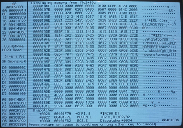
The first byte was $83, which was the command number plus $80. Afterwards followed a pile of other fields and flags, some of which I filled with sequences of consecutive numbers so I could recognize them in the debugger. But there were a few oddities, like the 14-byte break between 07 and 08 in the sequence on the second and third lines. At first I thought this was a bug in my sending code, but it turns out that the Mac actually stores it this way intentionally. I don’t know why, but from examining the ROM disassembly, it’s clear that after the first 26 bytes are received, it jumps the buffer pointer to a new address and stores the remainder of the data there.
The other odd thing about this memory dump completely escaped my notice at first. In the sequence ending on the 22nd line, notice how the last two bytes are FCFC? The expected continuation of consecutive values should be FCFD. This was a clue whose meaning I didn’t discover until later.
Unfortunately, the ROM routines don’t actually store the checksum byte itself, so I couldn’t use MacsBug to examine it and see why it was wrong. It was that FCFC value that finally led me to the answer. For reasons I still don’t understand, it appears that the last byte in a transmission I send from the Emu hardware to the Mac isn’t received correctly. The last byte contains the least significant bits of the preceding seven, which include the checksum byte. By appending an extra dummy byte onto the end of the transmission, the LSB byte was now received correctly, and the last seven bytes before it could be correctly reconstructed.
Once I made this fix, the test program started reporting something new: error -19, read error. And the Emu received a new command after #3 drive status: command #0, read block. The Mac had accepted my drive status reply, and was continuing on to perform a read request! Two way communication at last! Of course I hadn’t implemented a handler for block read requests yet, that was next. But it was time to take a break, and celebrate my progress to this point.
Here is the correctly-formatted drive status structure:
#define DEVICE_CHAR_DISK_IN_PLACE 0x02
#define DEVICE_CHAR_ICON_INCLUDED 0x04
#define DEVICE_CHAR_WRITE_PROTECTED 0x08
#define DEVICE_CHAR_EJECTABLE 0x10
#define DEVICE_CHAR_WRITABLE 0x20
#define DEVICE_CHAR_READABLE 0x40
#define DEVICE_CHAR_MOUNTABLE 0x80

struct DriveStatus
{
	uint16_t deviceType;
	uint16_t deviceManufacturer; // Apple = 1
	uint8_t  deviceChars; // characteristics
	uint8_t  numBlocks[3]; // 3 bytes number of blocks on device
	uint16_t numSpares;
	uint16_t badBlocks;
	uint8_t  reserved[52];
	uint8_t  icon[256];
	uint8_t  padding[16];
};
The structure is 336 bytes. A valid drive status response is:
$83 - command number plus $80
$00 - pad
$00 - status high byte, zero means no error
$00 - status low byte, zero means no error
$00 - pad
$00 - pad
DriveStatus struct
checksum - choose this so the sum of all bytes (including this one) is 0 modulo 256
This is 343 bytes. Then the response must be encoded using the 7-to-8 encoding method described in the DCD doc, and in my posting from last February. This results in 49 groups of 8 encoded bytes each that are actually sent to the Mac.
Checksum Non-Sequitur
Story time about checksum errors: my first computer was an Atari 800, which my family bought when I was 12. Day 1 when it arrived from the store, I attempted to load my very first program from cassette tape. The Atari reported “ERROR 143”. Confused, I consulted the printed manual to learn that error 143 meant “SERIAL BUS DATA FRAME CHECKSUM ERROR”. This was the full explanation, and the only help provided for the error. At the time, those words made as little sense to me as “BYTE VECTOR DIRECTION BUFFER INTERRUPT” might have, and I nearly threw the machine out the window. Fortunately it worked the second time I tried it, and my future in computer technology was assured.
Whee!
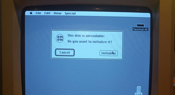
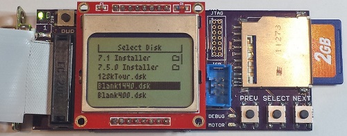
To prove that the drive status response was really working, I whipped up an ugly BMOW icon, and stuffed its bytes into the icon field of the DriveStatus struct sent from the Emu. Now when I try to mount the emulated HD20 in the Finder, I see the message shown in the photo at the top of this post. Woohoo, that is one ugly icon! But it comes from a successfully received drive status reply, so that makes it awesome.
There are still plenty of other issues to resolve before I can get full HD20 emulation working, not the least of which is actually implementing the read and write commands. Beyond that, here’s a strange one – if you move the mouse during a data transmission, it fails! The Mac ROM routines poll the SCC and VIA chips during HD20 transfers, and if there’s a pending interrupt, it puts the HD20 into a holdoff state so it can service the interrupt. I’m a little hazy on the details of how that works, and I haven’t yet tried to implement the holdoff logic. So for now if you move the mouse or do anything else to generate an interrupt, the transfer fails.
The bigger issues may be unrelated to the HD20 code itself. My current prototype uses the Floppy Emu hardware, but it replaces the Floppy Emu software rather than adding to it. In particular, I don’t think there are enough logic resources in the Emu’s CPLD chip to handle both floppy and HD20 emulation. This would mean you’d have to flash new firmware every time you wanted to switch between emulation types – not exactly a great user experience.
It’s also unclear which Macintosh models could make use of HD20 emulation. The Mac 512Ke and Mac Plus definitely have HD20 support in their ROMs. The Mac 512K can use an HD20 if you first boot it with a System file containing the HD20 Init – but that would require having a working floppy drive and floppy disk, or a second Floppy Emu to serve as the boot disk. According to mac512k.com, the Mac SE, Classic, IIci, and Portable also have HD20 support in ROM, but the SE/30, II, IIx, IIcx, IIsi, IIfx, and LC don’t. I assume that means anything newer than those machines doesn’t have HD20 support in ROM either. It’s not clear if newer machines could make use of the HD20 System Init, but if they could, they’d be subject to the same requirement of having a working floppy drive & disk or a second Floppy Emu for booting.
Even if HD20 emulation only proves useful to owners of the 512Ke, Plus, SE, Classic, Portable, and IIci, that’s still a lot of people! If any Floppy Emu owners with an SE/30, LC, or II-series machine other than the IIci would be willing to help test this, please let me know.
Read 6 comments and join the conversation68 Katy – 68000 Linux on a Solderless Breadboard
What does it take to build a little 68000-based protoboard computer, and get it running Linux? In my case, about three weeks of spare time, plenty of coffee, and a strong dose of stubborness. After banging my head against the wall with problems ranging from the inductance of pushbutton switches to memory leaks in the C standard library, it finally works! I’ve built several other DIY computer systems before, but never took their software beyond simple assembly language programs. Having a full-fledged multitasking OS running on this ugly pile of chips and wires is a thrill, and opens up all kinds of interesting new possibilities. I’ve named this plucky little machine 68 Katy.
Hardware
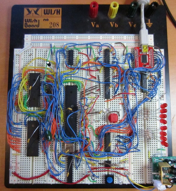
Here’s a look at the final version of the hardware. It took about a week to assemble and wire up all the parts on a solderless breadboard. The heart of the system is a Motorola 68008 CPU, a low-cost variant of the more common 68000, with fewer address pins and an 8-bit data bus. The CPU has 20 address pins, allowing for 1 MB of total address space. It’s paired with a 512K 8-bit SRAM, and a 512K Flash ROM (of which 480K is addressable – the remaining 32K is memory-mapped I/O devices).
The standard 68000 CPU has a 16-bit data bus, so it normally requires at least two 8-bit RAM chips and two 8-bit ROM chips. The 68008 requires fewer memory chips thanks to its 8-bit data bus, but the trade-off is that memory bandwidth is only half that of the 68000. Neither chip has any on-board cache, so half the memory bandwidth leads to roughly half the performance. My 68008 runs at 2 MHz (it was unstable when tested at 4 MHz), providing similar performance to a 1 MHz 68000. That’s pretty slow, even in comparison to 68000 systems from the early 1980’s, which were typically 8 MHz or faster.
An FT245 USB-to-FIFO module provides a communication link to another computer. On the external PC, it appears as a virtual serial port. Windows Hyperterm or another similar terminal program can be used to communicate with it, like an old VT100 terminal. On the 68 Katy side, the FT245 appears as a byte-wide I/O register mapped into the CPU’s address space. Reading from its address fetches the next incoming byte from the PC, and writing to the address sends a byte out to the PC. The FT245 has an internal 256-byte buffer, which helps smooth out the communication. When there’s an incoming byte waiting in the buffer, it triggers a CPU interrupt.
A 555 timer provides the only other interrupt source, generating a regular series of CPU interrupts at roughly 100 Hz. The initial version of the hardware had no timer interrupt, but I later discovered it was essential in order to get Linux working correctly.
The protoboard has eight LEDs for debugging, which are driven from a memory-mapped 74LS377 register. The rest of the protoboard is filled with assorted 7400 series parts and one PAL, which are used for address decoding, interrupt arbitration, and other basic glue logic.
Schematics? Forget it. Everything was built incrementally, one wire at a time, while staring at chip datasheets. It’s an organic creation.
Software
Once the hardware build was done, I began writing some simple test programs in 68K assembly language. Wichit Sirichote’s zBug monitor provided a good starting point for my own ROM-based monitor/bootloader. Using the monitor program, I was able to load other programs in binary or Motorola S-record format over the FT245 link, store them in RAM, and execute them. I was even able to get Lee Davison’s ehBASIC for 68000 working, which provided a few hours of fun.
One feature I could have added to the monitor program, but didn’t, was the ability to reprogram the Flash ROM. The ROM chip has a read/write input pin just like an SRAM, but writing to the Flash ROM is more complicated. The CPU needs to first write a magic sequence of bytes in order to unlock the ROM. Then it needs to write more magic bytes to tell the ROM which blocks to erase, followed by the new bytes to be written. Finally, it must poll the output of the ROM to learn when the erase and reprogram sequence is complete.
The monitor program could have updated itself, or any other data stored in ROM, by copying itself to RAM, then running from RAM while saving new data to Flash ROM. But I was lazy and never implemented that feature, so I had to physically pull the ROM chip from the protoboard and place it in an external EPROM programmer whenever I made a change – about 100 times over the course of the project. Ugh.
Linux
Inspired by a similar project, I decided that a simple monitor program and BASIC weren’t interesting enough, and I needed to run Linux on this hardware. It sounded interesting and exciting, but I really had no idea where to begin. I had plenty of experience as a Linux user (as well as other UNIX versions), but I knew nothing about how the kernel worked, or how to build it from source code, or to port it to new hardware. So the real adventure began there.
The first challenge was to learn how to build a Linux image for an existing machine. It seemed simple enough in theory – just download the source code from kernel.org or some other distribution tree, and compile it. Reality was more complicated, and there were many details that confused me, and build problems I was powerless to solve. It wasn’t easy, and I discussed the process in much more detail in this earlier post.
I chose to use uClinux, a Linux distribution designed for microcontrollers and other low-end hardware, particularly CPUs without an MMU and that can’t support virtual memory. Then I chose a very old version of uClinux, based on kernel 2.0.39, that dates all the way back to 2001! I configured it to disable nearly every single optional feature, including all networking support. This ancient code was my best hope for getting a Linux that would actually run in 512K of ROM and 512K of RAM.
Starting with the uClinux configuration for another 68000-based system, I updated the code to reflect the 68 Katy memory map, changed the system initialization code, and added a driver for the FT245. Describing those steps makes them sound simple, and they might have been for someone more experienced with Linux, but for me it was a challenge just to identify which files and functions needed to modified. Google wasn’t very helpful, since I was working with such an old version of the kernel, and the resources I found on building/porting Linux mostly weren’t applicable. I primarily relied on the Linux grep command to search through the thousands of kernel source files for strings of interest, then stared at the code until I could understand how it worked.
After about a week, I had something I was ready to test. And it worked, at least a little bit! It showed the first few lines of kernel output, but hung at “calibrating delay loop”. Aha, I needed a timer interrupt. Of course! I added a 555 timer and some extra interrupt logic, and was ready to try again.
The second attempt got further into the boot process, but failed to mount the memory-resident root filesystem. I was stumped for a while. After looking more carefully, I discovered that my linker script was mapping the root filesystem and BSS to the same address in RAM, and the earily initialization code was overwriting the filesystem with zeroes. And more fundamentally, I discovered that it wasn’t possible to fit all of Linux in 512K RAM, including the kernel code, static data, root filesystem, and dynamically allocated memory. Something had to be moved to ROM, or it was never going to work.
In the third attempt, I moved the root filesystem image to ROM, freeing up about 150K of RAM. And this kind of, almost worked! It booted, mounted the filesystem, and seemed to be working OK, but then suddenly it would land back at the monitor program prompt. Huh? I eventually tracked this one to the FT245 driver I’d written. I only implemented the minimal set of required driver functions, and the other optional functions were NULL entries in a function table somewhere. One of the functions I thought was optional proved to be required. When the kernel called it, it used a NULL function pointer, causing a jump to address 0, restarting my monitor program.
The fourth attempt was better. It spawned the init process, and ran the startup script, but died with out-of-memory errors before it completed. At the time, 68 Katy’s memory map was 256K ROM, 256K I/O devices, and 512K RAM. By shrinking the I/O space to 32K, I was able to increase the usable ROM to 480K, providing enough space to store the root filesystem image and the kernel code itself! This freed up another 251K of RAM.
The fifth attempt actually booted to a shell prompt! Now it was executing the kernel code directly from ROM. I was able to run a few commands, like ls and cat, but then the system would run out of memory and die. As I investigated, it looked like memory allocated from malloc() and do_mmap() was never beeing freed. Was this some kind of free list allocator I didn’t understand? No. It turns out I’d made a typo in a function called is_in_rom(), adding too many zeroes, causing the memory allocator to think all addresses were in ROM and so didn’t need to be freed. Then after fixing that, I discovered a small memory leak in the C library setenv() function. I never did solve that one, but instead just modified the programs that used it to avoid calling it.
My debugging method was primitive: lots of printk and printf statements sprinkled everywhere. Then pull the ROM chip, reprogram it in an external EPROM programmer, replace it in the protoboard, and try again.
The sixth attempt finally worked. Two weeks after beginning my experiments with Linux, I had a working system! Here’s a screenshot of the boot sequence:
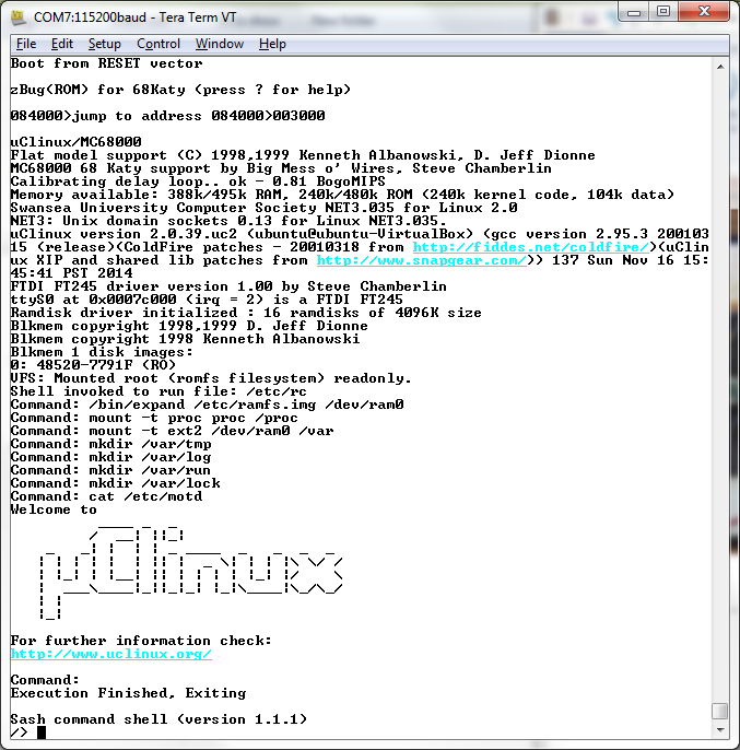
Watch the video for more details. I’m using a shell called sash, which has a few dozen common shell commands (like ls and cat) built directly into it. The root filesystem in ROM is read-only, and a small read-write filesystem is created in a RAM disk. The system supports multitasking, so it can run an LED blinker program in the background while still working in the Linux shell. It even has vi, and Colossal Cave Adventure!
It was an interesting journey. The Linux kernel still seems big and unwiedly to me, but no longer seems so scary as it did initially. It’s just an especially big program, and most of its pieces aren’t too difficult to understand if you open up the relevant source files and start reading.
Memory Requirements
So how much memory does it require to run a super-minimal uClinux system, with an old 2.0 kernel? If you follow my example and put as much as possible in ROM, it needs about 343K of ROM and 312K of RAM, or just 628K of RAM if you’ve got a bootloader that can fill RAM from some external source. My 68 Katy system is slightly heavier than that due to including vi and Adventure, but not by much. Here’s the breakdown:
ROM
- kernel code and read-only data (.text and .rodata segments) – 251K
- kernel initialized static data (.data segment) – 27K
- root filesystem – 189K
RAM
- kernel static data (.data and .bss segments) – 84K
- kernel dynamic allocations during boot-up – 104K
- RAM disk – 64K
- init and shell process allocations – 58K
- stack and exception vectors – 2K
Problems
The kernel always measures the CPU at 0.81 bogomips, regardless of the clock crystal I use. The 555 timer interrupt is independent of the CPU clock, so with a faster clock the bogomips calculation should measure more executions of the busy loop per timer interrupt. I’m not sure why it doesn’t, but it means any real-time calculations will be off.
The display in vi acts weird. Some lines appear prefixed with a capital H, and stray Unicode characters appear here and there. At first I thought this was a hardware bug, and I’m still not certain it isn’t. But I think it’s probably an issue with the way my terminal program (Tera Term) handles the ANSI escape sequences sent by vi. I tried all the different terminal settings available in Tera Term, and also tried a different terminal program, all with the same result.
What’s Next?
This 68008 system on a protoboard was intended to be only an experiment and proof-of-concept for the real 68 Katy, which I had planned to build on a custom PCB with a full 68000 CPU, a CPLD for glue logic, more RAM, an SD card, and ethernet. But this experiment was perhaps a bit too successful, and now I’m wondering if it really makes sense to go to the effort of building the “real” system if it’s going to be essentially the same thing, only faster. Of course the SD card and ethernet will add some interesting new elements, so maybe it’s fine. I probably need to sleep on the question for a few days.
One way of adding more spice to the next iteration of 68 Katy would be to include video output, so it could directly drive a monitor instead of being controlled through a serial terminal. I’ve done that once before, with BMOW 1, which had VGA output. It mostly worked, although the arbitration for video memory between the display hardware and the CPU was clunky and produced visible display artifacts. To take things further, I could even aim for DVI or HDMI video output, since VGA is a slowly dying standard.
The smart move is probably to stick with my original plan. Lots of extra features are cool, but also have a way of killing a project. I’d rather have something with 10 features and that works, than something with 20 features that I never finished or that collapsed under the weight of its complexity. But until then, excuse me while I go play some more Colossal Cave…
Files
The source code for my 68 Katy port of uClinux is available for download, as well as the toolchain I used to build it, the monitor/bootloader source, and a preconfigured VirtualBox machine image of Ubuntu 12.04 to host it all. Grab the files here. Have fun!
Floppy Emu, Year 1
It’s been roughly a year since I turned a personal electronics project into a retrocomputing mini-business, which makes now a good time for a short review. When I started dabbling in floppy disk emulators for vintage Macintosh computers, I never would have guessed there would be other people out there who wanted one of their own. It’s been an interesting adventure!
After selling a few prototypes on eBay, and giving away a few boards as gifts, the first real sale was board S/N #0008 on December 9, 2013. Since then I’ve made 223 Floppy Emu boards, sold 182, junked 4 that had defects revealed in testing, replaced 2 that had problems during the warranty period, and have 35 in inventory (aka my floor).
The first 123 boards were built by hand, one at a time, one component at a time. There’s not a lot to say about that experience except that it sucked, and I inhaled a lot of leaded solder fumes. Of those 123, there were 3 with major defects that had to be junked, and 4 more that only worked at 400K/800K disk speeds and were sold at a discount. Since serial number #0121, all boards are now professionally assembled by Microsystems Development Technologies in San Jose, CA. That’s helped improve the quality, and restore my sanity. Of the 55 boards from Microsystems that I’ve tested thus far, only one has had a defect.
Initially, all Floppy Emus were sold with a built-in DB-19 floppy connector, so the board could be plugged directly into a Mac’s rear floppy port. I later introduced a version with the DB-19 on a 3 foot extension cable instead of soldered directly to the board, and that’s proven to be very popular. Since mid-August when I lowered the price of the extension connector model by a few bucks, it has outsold the built-in connector model by 4:1. At some point I’ll probably drop the model with the built-in connector, and standardize on the extension connector model for all sales.
Cases for Floppy Emu have only been available for a short while, but they’ve been well-received. The attachment rate for cases (percent of people buying a board who also buy a case) has been 83%, much higher than I’d expected. And despite my predictions, the brown hardboard case has been much more popular than the clear acrylic case. I’ve already sold out of the hardboard cases, and just placed an order today to manufacture more.
About 50 percent of sales have been to the United States, which isn’t too surprising since that’s where I am. Australia, Canada, and the UK have also all seen significant sales. No sales to Africa or Antarctica yet, but all the other continents are represented.
Shipping has gone smoothly, even internationally. I’ve only had one shipment (to New Zealand) that never reached the buyer.
My order handling and fulfillment process is still horribly inefficient, but there aren’t enough sales to justify a big investment in streamlining things. Between manually testing each board on a Mac 512K and a Mac IIsi, downloading Paypal order details, fighting the post office web site to print electronic postage, generating sales receipts, wrapping boards, packing boxes, and driving to the post office, there’s about 30 minutes of labor time required for every single sale. Then there are often post-sale questions, which require additional support time. It’s not exactly a low-overhead business.
I’m excited to see what year 2 will hold for Floppy Emu. Thanks for coming along for the ride!
Read 2 comments and join the conversationBanging my Head Against the Wall
![]()
Still working on the uClinux bring-up for my 68000 protoboard machine. Still not there. Why is this so hard?
Yesterday the boot process was working up to the point where it tried to mount the root filesystem image. I finally got that sorted out, as well as the mistake I’d made in the available ROM size. I created a hybrid boot config that placed the filesystem image in ROM, and expected everything else to be preloaded in RAM by my monitor program. Finally I was ready to boot up all the way to a shell prompt! Alas, it wasn’t meant to be. Here’s what’s happening now – with a lot of debug prints added:
uClinux/MC68000

Flat model support (C) 1998,1999 Kenneth Albanowski, D. Jeff Dionne

KERNEL -> TEXT=0x080000-0x0b95d4 DATA=0x0bef18-0x0c5b50 BSS=0x0c5b50-0x0d3f53

KERNEL -> ROMFS=0x0c5b50-0x0c5b50 MEM=0x0d3f60-0x0fbe00 STACK=0x0fbe00-0x0ffe00

No Command line passed

Done setup_arch

start_mem is 0xd3f60

virtual_end is 0xfbe00

before free_area_init

free_area_init -> start_mem is 0xd6f60

virtual_end is 0xfbe00

MC68000 68 Katy support by Big Mess o' Wires, Steve Chamberlin

Calibrating delay loop.. ok - 0.81 BogoMIPS

Mem_init: start=db000, end=fbe00

Memory available: 128k/243k RAM, 0k/0k ROM (741k kernel code, 876k data)

Swansea University Computer Society NET3.035 for Linux 2.0

NET3: Unix domain sockets 0.13 for Linux NET3.035.

uClinux version 2.0.39.uc2 (ubuntu@ubuntu-VirtualBox) (gcc version 2.95.3 20010315 (release)(ColdFire patches - 20010318 from http://fiddes.net/coldfire/)(uClinux XIP and shared lib patches from http://www.snapgear.com/)) 48 Fri Nov 14 00:42:45 CET 2014

systctl_init

kernel_thread

idling...

init

setup

sys_setup

FTDI FT245 driver version 1.00 by Steve Chamberlin

ttyS0 at 0x00060000 (irq = 2) is a FTDI FT245

Ramdisk driver initialized : 16 ramdisks of 4096K size

Blkmem copyright 1998,1999 D. Jeff Dionne

Blkmem copyright 1998 Kenneth Albanowski

Blkmem 1 disk images:

0: 3000-25FFF (RO)

VFS: Mounted root (romfs filesystem) readonly.

sys_setup_done

still running.

open console

trying /etc/init

trying /bin/init

do_mmap:

Process blocks 1: 000dd2ec: 00000000 -> 000e60d8: 000e60f8 (20456 @000ee018 #1).

bdflush() activated...sleeping again.

Exit_mmap:

Process blocks 3: 000dd36c: 00000000.

do_mmap:

Process blocks 3: 000dd36c: 00000000 -> 000e6118: 000e6138 (12264 @000f5018 #1).

Jump to 0
zBug(ROM) for 68Katy (press ? for help)
084000>
It successfully mounts the filesystem, it starts the init process, there are a couple of memory allocations, and then suddenly I’m back at the monitor prompt. What the hell?!
There is no intentional mechanism by which uClinux can return control to the ROM monitor, but that’s what appears to have happened. But how? After doing some sleuthing, it looks like uClinux is jumping to address zero. Normally that would cause a crash, since the value at address zero is supposed to be the initialization value of the supervisor stack after a CPU reset, and not executable code. But my monitor program has a “feature” where it stores a branch instruction at address zero, and initializes the stack elsewhere. By making that branch instruction point to a different spot than the actual CPU reset vector, I was able to confirm that a jump to zero is happening, rather than an actual CPU reset or the kernel’s hard_reset_now() function.
The easiest way to accidentally jump to address zero is to overwrite part of the stack with zeroes while in a subroutine or interrupt handler. When the return address is popped off the stack, boom! The program goes to zero city. That can happen in a buggy program, or after a stack overflow. But those shouldn’t be concerns when running standard pieces of the Linux boot process, should they?
My fear is that this isn’t a software bug at all, but glitchy hardware behavior due to noise or failed timing constraints or poor electrical decoupling. I saw something very similar a couple of days ago, where the monitor program would reliably jump back to the command prompt whenever I tried to load a binary file, but before I actually started even loading the file. The problem disappeared when I removed a recently-added bypass capacitor from the protoboard. Hmmmm, not good.
But assuming for a moment that this is a software bug, let’s take a closer look at what’s happening right before it dies. Everything up to the line trying /bin/init is the kernel startup code talking. When it’s done initializing things, it launches the user-mode program init, which is the first real process. Init’s job is to start all the other user-mode processes, like the login shell and background services. Launching it is a big deal: the kernel needs to locate /bin/init in the filesystem, allocate memory, copy the program binary into the allocated memory, perform load-time patch-up of the program’s addresses given the physical address at which it was loaded (no virtual memory here), and finally start the program running as a new process to be managed by the scheduler. So it’s possible something’s going wrong there, but… this is the Linux kernel, it’s supposed to work. I thought that once I’d written my hardware-specific code, my porting job would be done. I didn’t expect to have to debug execve().
I’m not completely sure how to interpret those last mmap log entries, but I think it’s saying that process id 1 (that should be init) has a single allocated block of 20456 bytes at address 0ee018 with a refcount of 1. Then later there are a couple of lines from process 3, which seems to imply init successfully started some child processes. Or did it?
I’ll try adding some debug print statements to init to see what’s happening, as well as waving a dead chicken over the board to scare off any hardware gremlins lurking there. This is proving to be a tougher task than I’d planned for!
Read 16 comments and join the conversationInching Forward
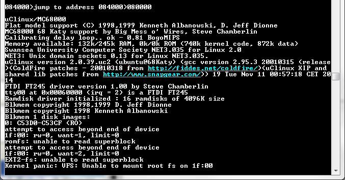
So close to a successful boot, yet so far away! I’m continuing to work on porting uClinux to my 68000 protoboard computer. Since my last post, I’ve added hardware to support timer and serial interrupts, and shrunk the linux boot image down to a petite 417K. The image is supposed to be ROM-resident, but because it takes so long to reprogram a Flash ROM, I’m using my monitor program to load the image into RAM and execute it from there. This requires editing the kernel linker script to assemble everything to RAM addresses, but it seems to work OK, and the result is shown above. Almost there!
Something goes wrong when it tries to mount the filesystem: either it’s using the wrong address (C53D0-C53CF looks suspiciously wrong), or there’s not actually enough RAM to hold the boot image plus .bss segment plus dynamic RAM allocations (why 16 ramdisks?). Probably it’s just out of RAM. Encouraged that it got so far in an all-RAM boot, I changed the linker script back to assemble code to ROM addresses, rebuilt the kernel, and burned a combined monitor+linux image to the Flash ROM. But when I try to boot uClinux from ROM, it does nothing. No output, no signs of life. I can use the monitor program to disassemble the code to make sure the addresses look right, and trace through the first few instructions, but that’s all. The monitor doesn’t support breakpoints, and even if it did, there’s no way to set breakpoints in ROM for the 68000. So I’m reduced to just staring at the code, trying to guess what went wrong. Discouraging.
If staring at the code doesn’t reveal the problem, the only other approach I can think of is a tedious one. I can add instructions to set the debug LEDs at various points in the linux boot code, then burn a new ROM and watch what the LEDs do when I try to start the kernel. That should work, but every time I need to add more debug instructions to narrow down the problem, it’ll be a 15 minute cycle of rebuilding the kernel image, pulling the ROM chip from the protoboard, burning the new image, and replacing the chip. Ugh.
Read 5 comments and join the conversationBaby Steps with uClinux
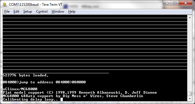
What you see above is my first attempt to boot a uClinux 2.0 kernel on the 68 Katy prototype hardware, the result of several days of work. It doesn’t look like much, but the fact that it even begins to boot up and print kernel messages is great! In the space of a few weeks, I’ve gone from knowing virtually nothing about the Linux kernel or Linux porting, to having a general idea how it should be done, to now having an actual build candidate that runs on the hardware. There’s still more work and more debugging to do, but I’m beginning to see the light at the end of the tunnel.
The boot process stalls at “calibrating delay loop..” because it’s trying to make a bogomips measurement, but there’s no timer interrupt. The CPU’s interrupt pins aren’t connected to any timer sources yet! One step at a time, and hopefully it’ll all still fit on the breadboard.
To reach this point, I had to get the uClinux 2.0 kernel source building with an existing board config (detailed in my previous post), then use that config as a template to make a new one for my hardware. It seems like that should have been fairly simple, since it only required changing the serial driver, memory layout, and a few config settings, but I found it challenging. Creating a serial driver was… interesting, and I probably did it all wrong. Then I used the Weiss SM2010 board as a template, which in hindsight may have been a poor choice. It’s the only board defined for the 68000 platform under kernel 2.0, so the line between 68000 platform generic code and SM2010 specific code is sometimes fuzzy. The result is something that’s more hackish than I’d like, but since I’m never going to merge these changes back, that’s probably OK.
I never found a detailed guide to porting, so I just had to search through hundreds of files to see which ones had been modified for SM2010, and then understand what they were doing and whether I should modify the code for my own board. If I were a nice guy, I’d write up a detailed how-to in order to save work for the next person who does this, but since it’s based on 10+ year old Linux source, it’s unlikely there ever will be a next person. Let’s just say there were dozens of little mysteries that had to be solved one-by-one, that I’m too tired to describe just now. 🙂 If anyone’s really curious, I’ll send you my notes.
Operating System, Meet Hardware
The final uClinux image is 829K, which is a problem given that the prototype machine only has 512K of ROM. So I did what any worthy hacker would do, and just truncated the file! That guarantees it will never boot correctly, but because the truncated portion was part of the rom-based filesystem image and not actual kernel code, it should at least boot to the point where it mounts the filesystem and tries to access it. When it gets that far, I have some ideas about how to shrink it down, hopefully to under 512K. I’m not sure how much RAM will be needed for a successful boot, or whether the 512K of RAM in the prototype will be enough. It looks like there’s about 35K of initialized data and 85K of uninitialized data (.bss segment). With the code itself stored in ROM, that still leaves 392K of RAM for dynamic allocations.
Did I say the code was stored in ROM? It will be, but for ease of testing I’m putting everything in RAM right now. I’ve got a simple monitor/bootloader in ROM, which in the screenshot above you can see performing the uClinux image transfer and initial jump. That makes it quick and easy to test new uClinux images, as compared to reprogramming the ROM chip for each test. But now that I think about it, there will never be enough RAM if I have to fit all the kernel code and data in there together. I’m going to have to burn a new ROM for each test. I might be able to improve things a little by giving the monitor program the ability to do in-system reprogramming of the ROM, instead of physically pulling the ROM chip from the board each time. Of course the monitor would have to avoid overwriting itself in the process.
The last major hardware task is interrupts, and there are a couple of challenges I’ll need to face. On the 68000, it’s not enough to just pull an IRQ pin low to start interrupt processing. When the pin is pulled low, the 68000 performs an interrupt acknowledge cycle, during which the interrupting peripheral is supposed to drive the vector number of its interrupt handler onto the bus. I have no circuitry to do that. The alternative is something called autovectoring, in which the vector number is determined automatically from the interrupt number. But I would still need some circuitry to assert the necessary control signals to request autovectoring during the acknowledge cycle.
The second interrupt challenge is clearing the interrupt. With the FT245 serial chip, this will happen automatically – the chip’s RXF signal will be deasserted after the CPU reads a byte from the FIFO. But for the timer, I’ll need to build a mechanism to explicitly clear the timer interrupt flag after the interrupt is processed. That normally wouldn’t be difficult, but I’m so low on board space and glue logic resources that I’m not sure how I’ll make it happen. It’s going to take some creativity to squeeze it all in there!
Read 10 comments and join the conversation