

Archive for April, 2017
Reflow Soldering with Hot Plate and Stencil
This was my 5th attempt to assemble some ROM-inator II boards using reflow soldering, instead of my normal drag-soldering with an iron. After various failures in the previous attempts, this time I used a stainless steel stencil to apply solder paste to the pads, hoping the stencil was the missing ingredient needed for success. I’ll save you the suspense: it didn’t work any better than my earlier efforts. I think I’m cursed.
You can read about the previous reflow attempts here:
1. Reflow with hot air
2. Switched to a hot plate
3. With an aluminum pie pan
4. New solder paste and aluminum sheet
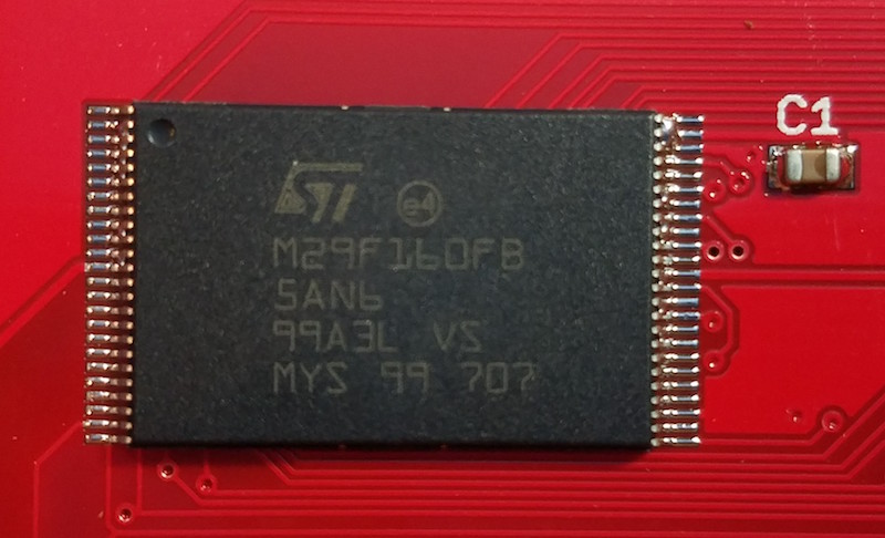
The ROM-inator II PCB has two chips with 0.5mm pin spacing, which makes home reflow particularly challenging. If my boards only had larger components, SOICs, and the like, my attempts would probably have gone much better. With the 0.5mm chips, no matter what method I tried, I ended up with numerous solder bridges between adjacent pins. I was able to fix up the solder bridges manually with an iron, so all the boards worked in the end, but reflow totally failed as a faster and easier replacement for drag-soldering. For that, I’d need boards to come out of reflow with zero solder bridges at least 80-90% of the time, and I was never anywhere close to that level of success.
Stencil Process
I ordered a 4 mil stainless steel stencil from OSH Stencils, and paid a little over $20 for the stencil and a couple of acrylic framing pieces. Ordering was easy, but I did run into a a few problems with my paste layer generated by EAGLE. The paste layer also contained my board outline, which I clearly didn’t want cut into the stencil. It also contained openings for all the edge contact pads on the PCB, which are not meant to be soldered. It required some extended futzing around in EAGLE in order to suppress the unwanted outline and pads, and generate a new paste file.
I taped the acrylic framing pieces to my desk, along with an extra blank PCB, to create a secure frame. Next, I placed a ROM-inator II PCB in the frame, and taped the stencil over it. Aligning the stencil correctly with the pads underneath was easier than I expected, even for the sub-millimeter sized pads. I then squirted some solder paste from a syringe onto the stencil, and used a plastic card to scrape the paste across the stencil, filling the holes.
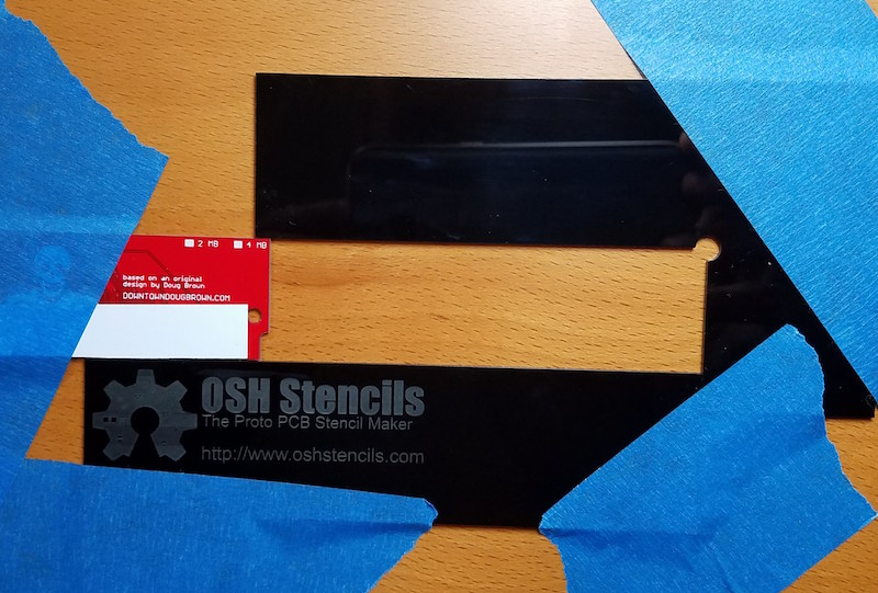
Framed area for PCB:
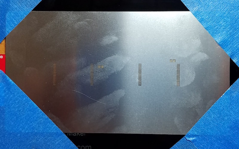
Blank PCB in frame:
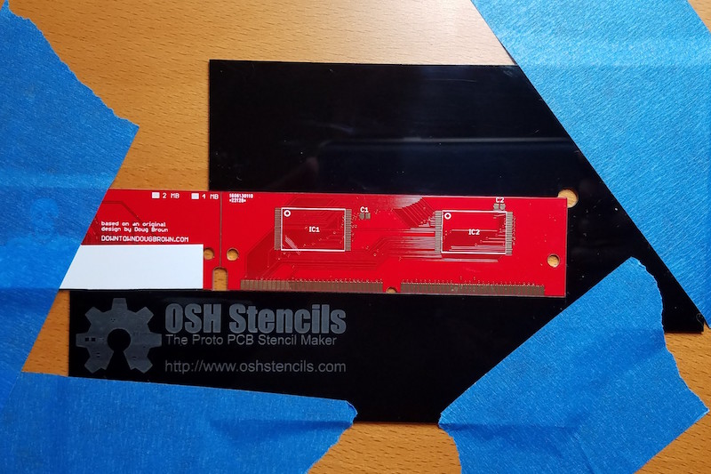
Stencil positioned on top of PCB:
Solder paste applied to the stencil:
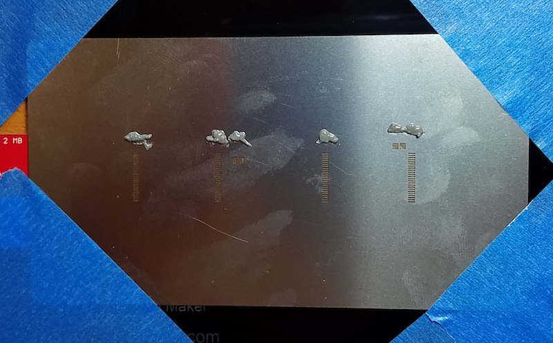
After scraping paste across the stencil:
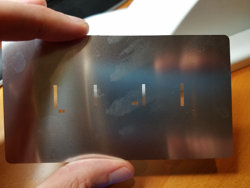
The PCB after removing the stencil:
Scraping the paste into the stencil openings was more difficult than I’d expected. I’d thought I would be able to make a single pass and fill all the holes, but some holes only partially filled with paste, even when there was plenty of paste scraped over them. Something to do with the thickness of the stencil, the size of the openings, or the viscosity of paste maybe? I had to make repeated passes from different directions with the plastic scraper before all the stencil openings were filled evenly.
One problem I hadn’t anticipated was the thickness of the acrylic framing pieces. They’re about 1.5mm thick, but the ROM-inator II PCB is only 1.2mm thick, resulting in the stencil floating 0.3mm above the PCB. 0.3mm may not sound like a lot, but it’s about 3x the thickness of stencil. In practice, the stencil flexed enough that it mostly sat flush on top of the PCB, but it clearly wasn’t ideal.
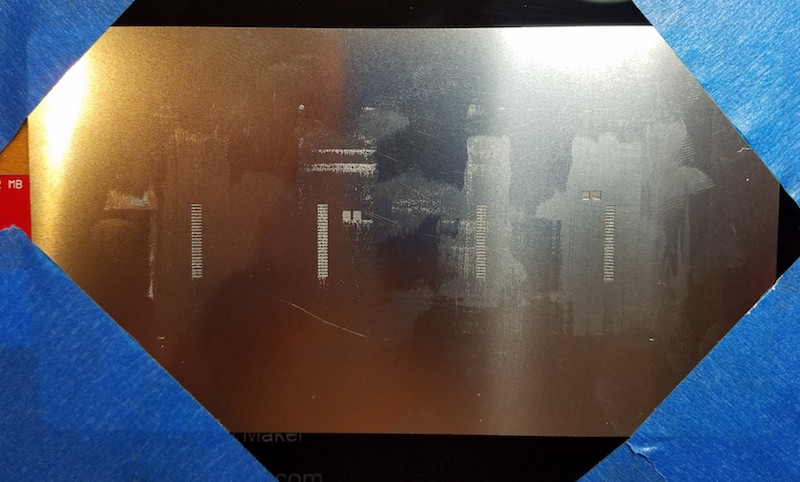
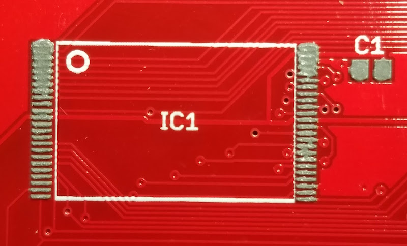
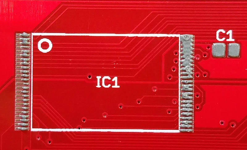
The final photo above shows the mixed results of solder paste application. For larger things like the C1 capacitor, it was great. And for many of the individual pads on chip IC1, there was a nice clear line of paste right on the pad. But for many other pads, the solder paste was smeared between several adjacent pads. Not good.
The final difficulty was placing the chip on the pads. Even where I had clean lines of paste, it was difficult to position the chip accurately without smearing the paste around in the process. I would drop the chip down with tweezers, close to where it needed to go, but “close” wasn’t close enough. Even a tiny sub-millimeter nudge to line up the chip properly was enough to smear paste from one pad to the next, possibly negating the whole benefit of using a stencil in the first place. Here’s what things looked like after placing the chip, but before reflow:
Results
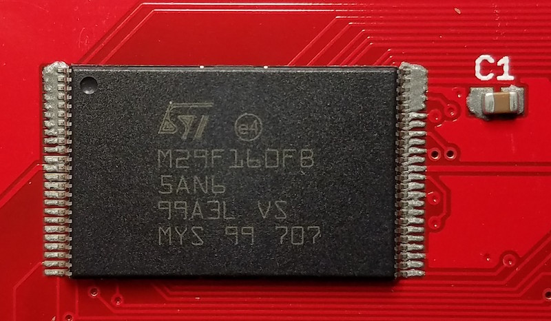
The result was similar to all my previous attempts: lots of solder bridges. Not surprisingly, most of the bridges showed up in those areas where the solder paste was smeared before reflow, but some bridges appeared even in areas where the paste had looked OK. Here’s how the same chip looked, after reflow with the hot plate:
I tried a second PCB, this time attempting to use less solder paste overall, but the results were the same. Then I tried a third PCB, and scraped the solder paste across the stencil left-to-right, parallel to the orientation of the pads, instead of perpendicular. That resulted in some weirdly uneven application, and more of the same solder bridges after reflow.
I could never get the solder paste application to come out cleanly, and it always seemed like too much.
Conclusions
At this point I’ve run out of blank ROM-inator II PCBs, so my experiments will have to stop for a while. I hate to end a series on a down note, but I’m a little frustrated and disappointed with this whole effort. Maybe I would get better results with thinner frame pieces, or a toaster oven instead of a hot plate, or yet another brand of solder paste, or a different paste applicator, or more flux, or a pick-and-place, or… but at some point I have to admit this just isn’t working. Once I get more blank PCBs to play with, I’ll consider whether to try further experiments.
Read 8 comments and join the conversationBootstrapping Apple //c with Floppy Emu
Thanks to Floppy Emu fan Andru Luvisi for contributing a great trick for bootstrapping an Apple //c with Floppy Emu. The Apple II family computers can normally only boot from Disk 1, but when Floppy Emu is connected externally to a //c and configured in 5.25 inch emulation mode, it becomes a non-bootable Disk 2. Until now, the options for making Floppy Emu bootable on a //c were:
- Switch the Emu’s emulation mode to Smartport hard disk, which is bootable
- Boot from a real 5.25 floppy in Drive 1, and then access the Emu as Drive 2
- Connect the Emu internally, in place of the real 5.25 inch floppy drive
- Use an A/B switch cable to connect the Emu and the real 5.25 inch floppy drive internally
Andru has devised a method for booting the //c from the Floppy Emu while it’s connected externally and configured in 5.25 inch emulation mode. In other words, it’s a method for booting from Disk 2 – something that’s normally impossible. This is great for the scenario where you want to make a bootable ProDOS floppy, and you’ve got a Floppy Emu, but no real floppies with a bootable DOS. Now it’s possible to boot from the Emu externally, then put a blank floppy in the //c’s internal drive and copy ProDOS to it.
- Connect Floppy Emu to the //c’s external disk port, and turn on the computer.
- The //c will display a CHECK DISK DRIVE error.
- Select ProDOS v1.9 from the Floppy Emu’s disk selection menu.
- Press CTRL+RESET on the //c keyboard to get a BASIC prompt
- At the ] prompt, type CALL -151 and press RETURN
- At the * prompt, press CTRL+E, then press RETURN
- You’ll see a line of text like M=00 A=08 X=00 Y=00 P=00 S=B7.
If the line of text begins with M, then type
:0 E0 60 1 and press RETURN
Else if the line of text begins with A, then type
:E0 60 1 and press RETURN - Type C60BG and press RETURN
The //c will immediately begin booting ProDOS from Drive 2!
Andru developed this method by examining code from Apple //c ROM version 255, which includes this feature natively as PR#7. The above monitor hacking makes it possible to do the same thing on other ROM versions of the Apple //c.
I was successful using this method with ProDOS v1.9, as well as with a few other utilities and games. Unfortunately most games won’t work using this method. They’re hard-coded to expect booting from Drive 1, so if you try this method they’ll start to boot from Drive 2, but then you’ll hear Drive 1 suddenly begin to grind away, and the game will freeze or display an error. Despite this limitation, booting 5.25 inch disk images from Floppy Emu as Drive 2 is still a very handy trick!
Read 1 comment and join the conversation