

Archive for the 'Floppy Emu' Category
1.4 MB High Density Floppy Emulation
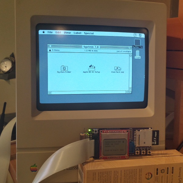
WOOOOO! Floppy Emu’s last big goal has been reached, and 1.4 MB disk emulation is now working! The photo shows a Mac Classic, booted into System 7.0 from a 1.4 MB high-density disk image. Combined with other recent improvements, this means Floppy Emu now works for 400K, 800K, or 1440K disk images in raw .dsk or DiskCopy 4.2 .image format, on any Mac from the 128K to the Mac II series and beyond.
1.4 MB disk support proved to be very similar to 400K/800K support in concept, but completely different in details. Data on 400K/800K disks is stored using a technique called GCR, which dates all the way back to the Apple II. GCR defines how data is encoded as flux transitions on a magnetic disk (or an emulated version of one, like we have here). In contrast, 1.4 MB disks store data using a technique called MFM, which is used by PCs as well as other classic systems including the Amiga and Atari ST. While GCR and MFM serve the same purpose, they are quite different, so Floppy Emu’s microcontroller and CPLD software both had to be extensively modified to add MFM support. For the curious, this Atari ST page has an outstanding explanation of floppy data encoding and MFM, almost all of which is relevant to the Macintosh too.
Aside from the MFM encoding change, another big challenge was maintaining MFM’s higher data rate. A Macintosh 400K or 800K floppy sends bits to the floppy controller at 500 kHz, but a 1.4 MB floppy sends bits at 1 MHz! That means Floppy Emu’s AVR microcontroller and companion CPLD needed to work twice as fast as before to serve data to the Mac, or else an underrun error would occur. My first attempts resulted in something that was almost but not quite fast enough, leading to a maddening situation where data transfers seemed to work much of the time, but would flake out with seemingly random errors before an entire sector could be transferred. In the end I had to review the C compiler’s assembly output, and do some cycle counting by hand, in order to optimize the code to the point where it was fast enough to consistently meet the data rate demands.
Beyond the MFM differences, high density Mac disks also use a different signature than 800K disks for tagging sector address and data blocks, and use a different checksum algorithm. 800K disks use a near-incomprehsible checksumming algorithm that was probably invented by Woz himself, while HD disks use a standard CCITT-CRC16 algorithm. Then just for laughs, high density disks also use a 1-based numbering scheme for sectors, instead of 0-based. That little twist took me quite a while to recognize!
The last hurdle was related to the larger size of a high-density floppy track, and I still don’t have a perfect solution for it. For 800K disks, the number of combined sectors on both sides of a track is variable, but is never more than 24. With 512 byte sectors that’s 12K of data – small enough to fit into the microcontroller’s 16K of RAM with some room to spare. But for high-density disks, there are 36 sectors and 18K of data – it won’t fit! Instead of buffering an entire track in RAM, then, I had to fall back to the technique I originally used for 800K disks, and do SD card transfers on the fly at the instant the data is needed. It works well enough when reading the disk image, but when writing it’s very sensitive to the speed and variability of the SD card transfers.
There are still many little bugs to fix and things to polish, and a few other features I’d like to add, but with the addition of 1.4 MB support I think Floppy Emu is effectively finished. Or if not finished, at least worthy of a “1.0” version number release. My next plans are to polish up the code and documentation, squash a few more bugs, and then build some Floppy Emu units for those who want one. Happy hacking!
Read 5 comments and join the conversation
Fixing 30 Year Old Apple ROM Bugs
After nearly a year of inactivity, I’ve started work on Floppy Emu again! One of my first priorities was compatibility with Macs that have a 400K floppy drive – the original Mac 128K, and the Mac 512K (not the 512Ke). Floppy Emu emulates a 400K/800K external floppy drive, and it works fine with 400K disk images, so I originally assumed it would have no problems on those old 400K-based machines. Wrong! Reports trickled in of mysterious Sad Mac errors and other problems when using Floppy Emu with those oldest Mac models. After ignoring the problem for months, I finally got ahold of a Mac 512K so I could investigate things firsthand.
Some brief experimentation showed that Floppy Emu was at least partly working with the 512K. When I “inserted” a disk image of a non-bootable disk, the Mac rejected it and showed the X’d disk icon. But when I inserted a bootable 400K system disk image, the Mac chewed away for a moment, then died with a Sad Mac error code 0F0004. So it was clear the Mac 512K could recognize the difference between a bootable and a non-bootable disk, but was failing to actually boot when using Floppy Emu. The same disk image and Emu hardware booted fine on a Mac plus, so the problem looked like an unknown incompatibility between the Mac 512K and Floppy Emu.

The Sad Mac – such a cute way for a computer to die. Much friendlier than a blue screen of death, but just as fatal.
From past experience, I knew the Mac 128K and 512K used a different version of the Apple ROM than found in the 512Ke and Mac Plus. The 512Ke/Plus ROM added support for 800K floppy drives. But as long as only 400K disk images are used, I couldn’t see any reason Floppy Emu shouldn’t work on 128K/512K Macs with the old ROMs. After all, how would the Mac even know that Floppy Emu wasn’t a 400K drive? The real 400K and 800K drives are virtually identical, with the same connector, same internal registers, etc. The only difference is that one is a single-sided drive and one is double-sided. Also the Mac directly controls the speed of a 400K drive with a PWM signal, but an 800K drive ignores the PWM signal and self-regulates its speed.
I hunted the internet for details on 30-year-old boot errors, and found two explanations for error 0F0004. One said “Voltage too Low, adjust voltage to +5.0v.” and another said “Division by Zero”. How could there be two such radically different meanings for the same error? But things started to fall in place after I found this Apple Tech Note, which said that 0F0004 was a result of using an 800K external disk drive on the Mac 128K/512K with the old ROMs. So somehow the Mac was still identifying Floppy Emu as an 800K disk drive, which caused it to die. But how did it know?
ROM Diving
When all else fails, it’s time to look at the source code. In this case that meant disassembling the ROM from the 128K/512K to find out what the floppy driver is doing. I’ve done this a few times before now, but it’s still a major pain. Even with a 68K disassembly tool, and substituting symbolic names for all the Mac memory-mapped hardware, it’s still an opaque mess of assembly language code that doesn’t yield its secrets easily. It’s hard enough just to locate the relevant floppy routines, let alone understand the fine details of how they work. But after a day of poking and prodding, I found some code that looked very suspicious:
P_Sony_MakeSpdTbl:
1E82   285F                  Move.L    (A7)+, A4
1E84   343C 0080             Move      $80, D2		; set PWM value to $80
1E88   615C                  Bsr       P50		; measure TACH speed, get speed1 result in D4
1E8A   6B56                  BMI       L309
1E8C   2604                  Move.L    D4, D3		; copy result to D3
1E8E   343C 0100             Move      $100, D2		; set PWM value to $100
1E92   6152                  Bsr       P50		; measure TACH speed, get speed2 result in D4
1E94   6B4C                  BMI       L309
1E96   2A04                  Move.L    D4, D5		; copy result to D5
1E98   9A83                  Sub.L     D3, D5		; D5 = difference between speed1 and speed2
1E9A   E38B                  LsL.L     $1, D3
1E9C   7C04                  MoveQ.L   $4, D6
1E9E   4BFA FFC8             Lea.L     DT19, A5
1EA2   6100 FCA2             Bsr       Sony_SetupSonyVars
1EA6   47F1 101A             Lea.L     $1A(A1,D1.W), A3
1EAA   7400       L304:      MoveQ.L   $0, D2
1EAC   341D                  Move      (A5)+, D2
1EAE   2E02                  Move.L    D2, D7
1EB0   D45D                  Add       (A5)+, D2
1EB2   E24A                  LsR       $1, D2
1EB4   D484       L305:      Add.L     D4, D2
1EB6   9483                  Sub.L     D3, D2
1EB8   6A02                  BPL       L306
1EBA   7400                  MoveQ.L   $0, D2
1EBC   EF8A       L306:      LsL.L     $7, D2
1EBE   6702                  BEQ       L307
1EC0   84C5                  DivU      D5, D2		; divide D2 by (speed2 - speed1)
Comments were written by me, after analyzing the code. This particular routine does some kind of calibration of the floppy drive – it varies the PWM signal, then measures the resulting drive speed as indicated by a value called TACH. I think it’s trying to establish a linear relationship between PWM and TACH, since that relationship may vary slightly between real 400K drives. There’s a lot going on in this routine, and I’ve truncated it to only show the first 25 instructions. But notice it contains a DivU instruction? There aren’t many places that division is used in the original Mac ROM, so that’s significant.
Looking deeper, the routine makes two drive speed measurements, then does some math to compute a value in D2, then finally divides D2 by the difference between the two speed measurements. But what happens if the two speed measurements were equal? Division by zero! Hello, 30 year old ROM bug.
On a 400K drive that’s controlled by the Mac’s PWM signal, the speed measurements will always have different results, because the PWM is different during each measurement. But on an 800K drive which self-regulates its speed, and on Floppy Emu which has a totally fake speed, the PWM changes will have no effect. That means both speed measurements will get the same result, and the Mac will crash with a division by zero error when it calls this ROM routine. Getting two different speed measurements was probably a safe assumption in 1983/1984 when the code was written, but it still would have been nice to do some defensive programming and add a zero check there, to handle the case of a broken drive or broken assumptions.
Fixing It
Once I understood the cause of the 0F0004 error, the question was how to modify Floppy Emu to avoid it. The TACH speed signal that Floppy Emu generates is obviously fake, since there are no moving parts. It calculates how fast the drive motor should be spinning, given which track is being accessed, and creates a series of pulses on TACH at the appropriate rate. To avoid the division by zero crash, the TACH rate needs to vary, so that two successive measurements see different TACH speeds.
One solution would be to use the PWM signal from the Mac, since that’s its purpose. By analyzing the PWM duty cycle, the Floppy Emu hardware could infer how fast the Mac wanted the drive to spin, and generate an appropriate TACH to match. Unfortunately, the hardware doesn’t even have the PWM pin connected. And if it did, it’s not certain that it could do the necessary duty cycle and TACH calculations fast enough, or efficiently enough to fit in the remaining logic space.
My solution was to constantly flutter the drive speed TACH signal. The flutter rate must be fast enough that two successive measurements will see different rates, but not so fast that two successive measurements will span the entire flutter cycle and so see the same rate. The flutter amplitude must be large enough for the speed measurements to be different, but not so large that the measured speed falls outside the valid range for the current track being accessed. With a little experimenting, I settled on a flutter cycle period of 640 ms and a flutter amplitude of about 0.25%.
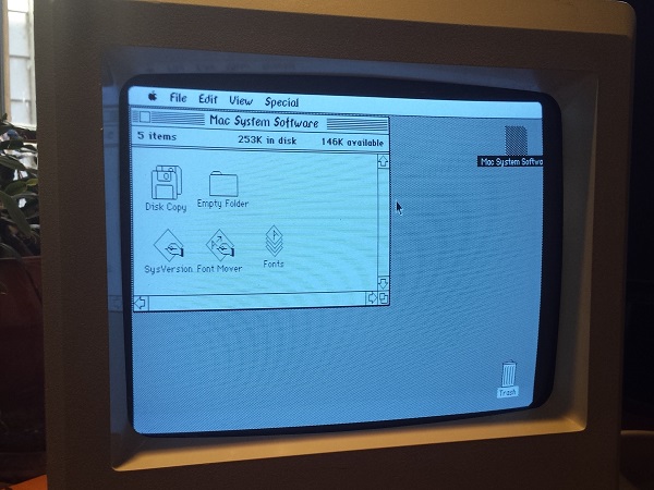
And it works! The image above shows the Mac 512K running System 0.97, Finder 1.0, booted from Floppy Emu. Those fonts sure are weird.
A Bit of History
When Macintosh external 800K floppy drives first became available, in 1985/1986, owners of the Mac 128K and 512K faced the same problem I did here, only they couldn’t modify the drive’s TACH behavior to work around the ROM bug. Instead, Apple released a system patch called HD20 which fixed the bug and added 800K drive support. But using it was a pain: you had to boot from a 400K floppy in the internal drive first, which contained the HD20 patch, and then you could mount an 800K floppy in the external drive. Booting from an 800K drive wasn’t possible. It wasn’t a very nice solution.
If that ROM routine’s author had added a zero check, this wouldn’t have been necessary. Mac 128K/512K owners could have booted directly from an 800K floppy in the external drive, loading the HD20 init in the process. Everything would have been great. Instead, that divide by zero bug doomed them all to a miserable 800K experience.
When Apple and Sony were developing the 800K external drive, they must have known this was a problem, and they could have used the solution I did to flutter the TACH speed. In 1985 they couldn’t just drop a 25-cent microcontroller into the drive to synthesize TACH, but they could have added a simple RC circuit to inject some AC “noise” into the TACH signal at the appropriate amplitude and period, achieving the same result. Everything would have been great. But they didn’t, and all those 128K/512K owners were forced to endure the 400K floppy boot-swap dance forever.
Read 5 comments and join the conversation400K Floppy Support
I’ve added 400K floppy support to Floppy Emu, so now you can boot up System 1.1. The fix took all of fives minutes, so why didn’t I do this ages ago? Grab the latest Floppy Emu file archive for the new software.
Read 3 comments and join the conversationFloppy Emu Disk Menu
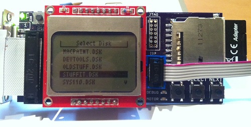
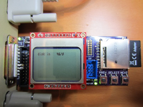
I finally got around to building a proper floppy disk image selection menu. Instead of loading a hard-coded rfloppy.dsk disk image file from the SD card, Floppy Emu now scans the SD card for all files with a .dsk extension, and displays a menu of available disk image files. The PREV/NEXT buttons navigate the menu, and the SELECT button inserts the selected disk image into the virtual floppy drive.
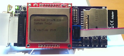
When a disk image is inserted, the LCD displays the name of the Macintosh volume that’s inside the disk image – “System Tools” in the example above. It also shows the current track and side being accessed. For write operations, the LCD displays the track, side, and sector that was written, as well as the time required for the write.
Download the Floppy Emu file archive for the new firmware.
Be the first to comment!
Finally!
The new Floppy Emu prototype is up and running at last! Today I was able to boot a Mac Plus from the new emulator board for the first time. It’s still rough around the edges, but it works. Copy a Macintosh disk image to your SD memory card, then plug the Floppy Emu board into your Mac’s external floppy port, and presto: instant disk drive. Your vintage Mac never even knows it’s not the real thing, so everything runs just like it would with a real external floppy drive.
It’s hard to believe it was nearly five months ago that I set out to replace my first ball-of-wires breadboard prototype with something better. The changes seemed simple enough: switch to a more powerful microcontroller from the same family, substitute a different brand of CPLD, add a few more buttons and connectors, and mount the whole thing on a small circuit board. But then I let the project gather dust for a few months, and when I returned to it, almost everything that could possibly go wrong did. Seemingly minor changes to clock speeds and interrupt configurations led to all kinds of head-scratching failures. They’re not interesting enough to detail, but you can imagine a string of long evenings filled with me pounding my fist on the desk and shouting rude things at the monitor.
One of the coolest features of the new board is that the microcontroller can program the CPLD via JTAG, using the XSVF player code that I discussed in my previous post. Copy a firmware.xvf file to the SD card, reset the Floppy Emu board while holding down both PREV and NEXT, and the CPLD will be updated with new firmware in about 20 seconds. That means an external Xilinx programmer isn’t needed at all, which is a huge win. I hope to later implement bootloading of the microcontroller from the SD card too. If I ever reach the point of selling assembled units, that means end users could update both the CPLD and the MCU just by copying the necessary files to the SD card, without any programming hardware at all.
There’s still a lot left to do. I haven’t yet tested write emulation with the new prototype, so that’s the first task. It should work, but it took me so long to get read emulation working that I wanted to savor the success for a while before enabling and testing the write emulation code. Then I’ll look at some new buffering schemes for write emulation, using the extra RAM found in the ATMEGA1284P microcontroller that the new prototype uses. That should hopefully make write emulation more reliable than in the first prototype. At some point, I also need to add support for 400K and 1.4MB floppies, since the current emulator is 800K only.
The user interface needs improvement too. I’d like to add a nicer way to trigger CPLD programming, and a menu to select from among many disk images on the SD card. It would also be nice to add features like an auto-insert option, to insert a particular floppy image into the virtual drive immediately when Floppy Emu is first powered on.
Two features that you probably won’t see are emulation of more than one floppy drive at a time, and emulation of disks larger than 800K (or 1.4MB on those machines that support it). Those limitations come from the Macintosh floppy driver code in ROM, so to change them I’d need to write a new driver, and find a way to load it using the built-in driver so that the new driver replaces the built-in driver after loading. In fact, I’d probably need to write a new driver for every Macintosh model, since they don’t all access the floppy hardware the same way. It’s all theoretically possible, but would be a major software project that I’d prefer to leave to someone else to attempt.
To my friend Tom who keeps hounding me asking when Floppy Emu will be ready, here you go. Your Mac 512K can now live again!
Read 16 comments and join the conversation
In-System CPLD Programming Using XSVF Files
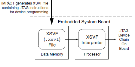
Floppy Emu has both a microcontroller and a CPLD working in tandem, and both must be programmed in order for the emulator to function. However, I don’t want to require two separate external programmers and the associated port connectors. My plan is to use a standard external ISP programmer for the microcontroller, but have the microcontroller program the CPLD, using the technique described in Xilinx app note XAPP058. The idea is to have the microcontroller act as an XSVF player, loading the CPLD configuration file from the SD memory card, and bit-banging the four JTAG pins on the CPLD to perform the programming.
This week, I finally got around to working on the XSVF player so I could program the CPLD on the Floppy Emu prototype board. The Xilinx player sample code is written in C, and was fairly easy to integrate into the emulator program. Using the functions I’d previously implemented, it was quick work to add an option to load a config file from the card and execute it with the XSVF player.
Predictably, once all the pieces were in place, it didn’t work. I spent a while checking and re-checking all my assumptions, reviewing the code, and writing debug info to the LCD, but made no progress. Finally I used the oscilloscope to peek at the JTAG signals, and discovered that they weren’t wiggling at all. All four JTAG signals were stuck high. I spent a few more hours chasing various theories why that might happen, and double-checked the electrical connectivity, before I gave up to do something else. Immediately after leaving the room, I suddenly realized what the problem was: in order to programmatically control the microcontroller JTAG pins, the JTAGEN fuse must be turned off, to disable hardware JTAG. Once I did that, the signals began wiggling as expected when I ran the XSVF player.
At this point the outgoing TMS, TCK, and TDI signals looked reasonable, but the JTAG communication still didn’t work. The error code from the player indicated that the TDO data returned from the CPLD didn’t match what was expected. Again the scope proved useful, this time by showing that TDO was stuck low, and never changed its value. No wonder the data didn’t match what was expected– it was always zero.
Here’s where I would normally describe how I finally solved the problem and got everything working, except this time I didn’t. At this moment TDO is still stuck low, and CPLD programming or other JTAG communication is not possible. I’ve examined the TMS, TCK, and TDI signals, and they look reasonable, and appear to roughly match the output of the PC-based XSVF player simulator that’s part of the Xilinx sample. So what might be wrong? Some theories, none of them great:
- The CPLD’s JTAG controller might not be active. But according to the datasheet, “If the device is in the erased state (before any user pattern is programmed), … the JTAG pins are enabled to allow the device to be programmed at any time. All devices are shipped in the erased state from the factory.”
- The JTAG controller might be in the wrong state to respond to the commands from the XSVF player. However, I looked at the code, and the first thing it does is reset the controller (by setting TMS high and pulsing TCK five times). This should be OK.
- The communication from the XSVF player might be garbled or broken. Maybe I accidentally swapped two signals, or introduced a bug in the player code? My preliminary scope debugging shows the signals look OK, so I’m skeptical this is the problem.
- The JTAG clock might be too fast. Initially the player code resulted in a JTAG clock rate around 500 kHz. I tried slowing it to under 1 KHz with no success.
- The player might not be waiting long enough for CPLD internal operations to complete. There’s a fairly long discussion of this in the sample code, and I’m fairly sure I did it correctly. When I tried slowing down the player even further, it didn’t help.
- The XSVF file might be bad. I’m using a file I generated with Xilinx iMPACT, which should simply query the device ID, then terminate.
- There might be an electrical short between TDO and ground. I’m fairly certain this isn’t the case, because before I disabled microcontroller’s JTAGEN fuse, TDO was about 4.5 volts. Now it’s zero. If there were a short to ground, it would have always been zero.
- The CPLD might be installed backwards or rotated, so the board trace isn’t actually connected to the TDO pin. I double-checked the orientation, and it looks correct.
- The CPLD might be damaged or defective.
For the moment at least, I’m stumped. I’m out of ideas for other things to try. I’m going to set this aside for a while, and hope that the solution will suddenly occur to me while I’m working on something else. Or failing that, I may at least come up with new theories that can be tested. Debugging electronics sure can be a pain!
Read 8 comments and join the conversation